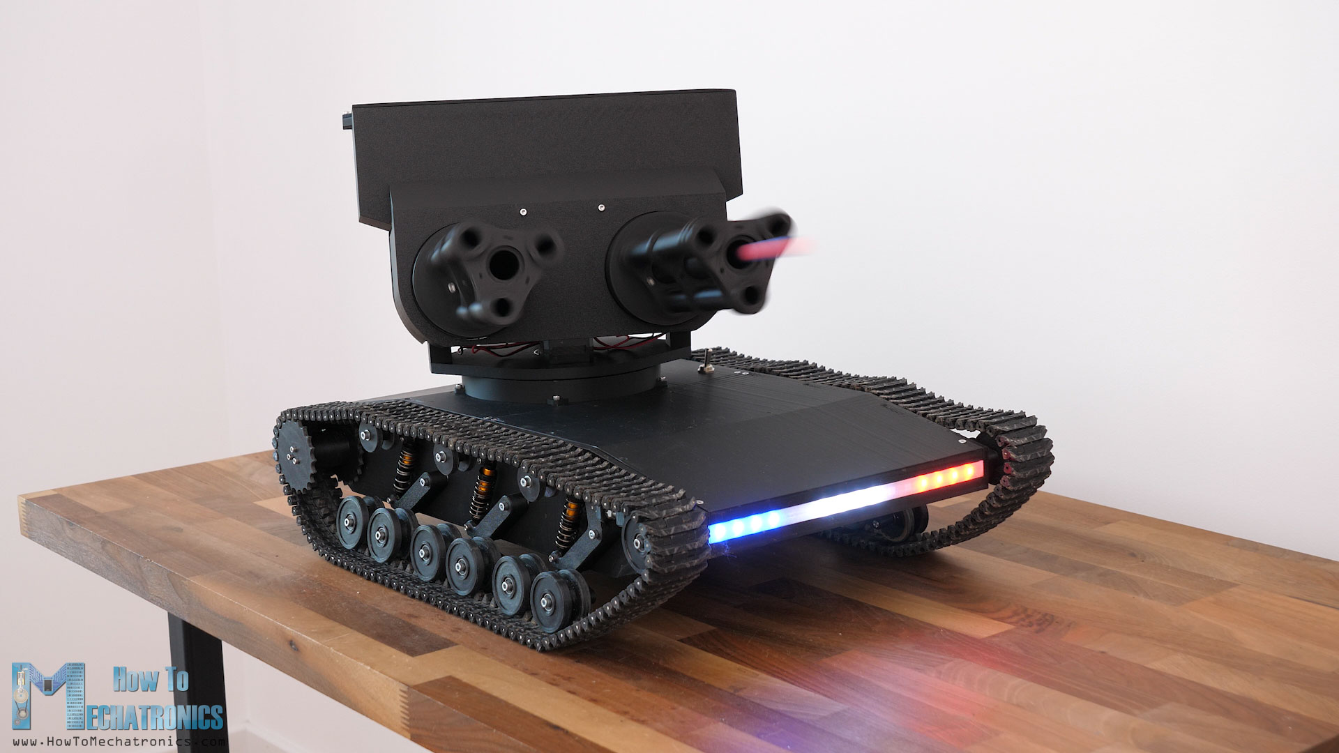
In this tutorial I will show you how I build this double-barrel nerf minigun turret for the 3D printed tank that I build in one of my previous videos. Spoiler alert, the minigun or the gatling gun is actually fake, but it makes this tank looks super cool and fun to play with.
You can watch the following video or read the written tutorial below.
Overview
The turret has a magazine that can hold around 200 nerf darts and it can fire all of them in around a minute. That’s a firing rate of around 200 darts per minute. The darts can fly at a speed of around 50m/s. That provides a distance range of around 12 meters.
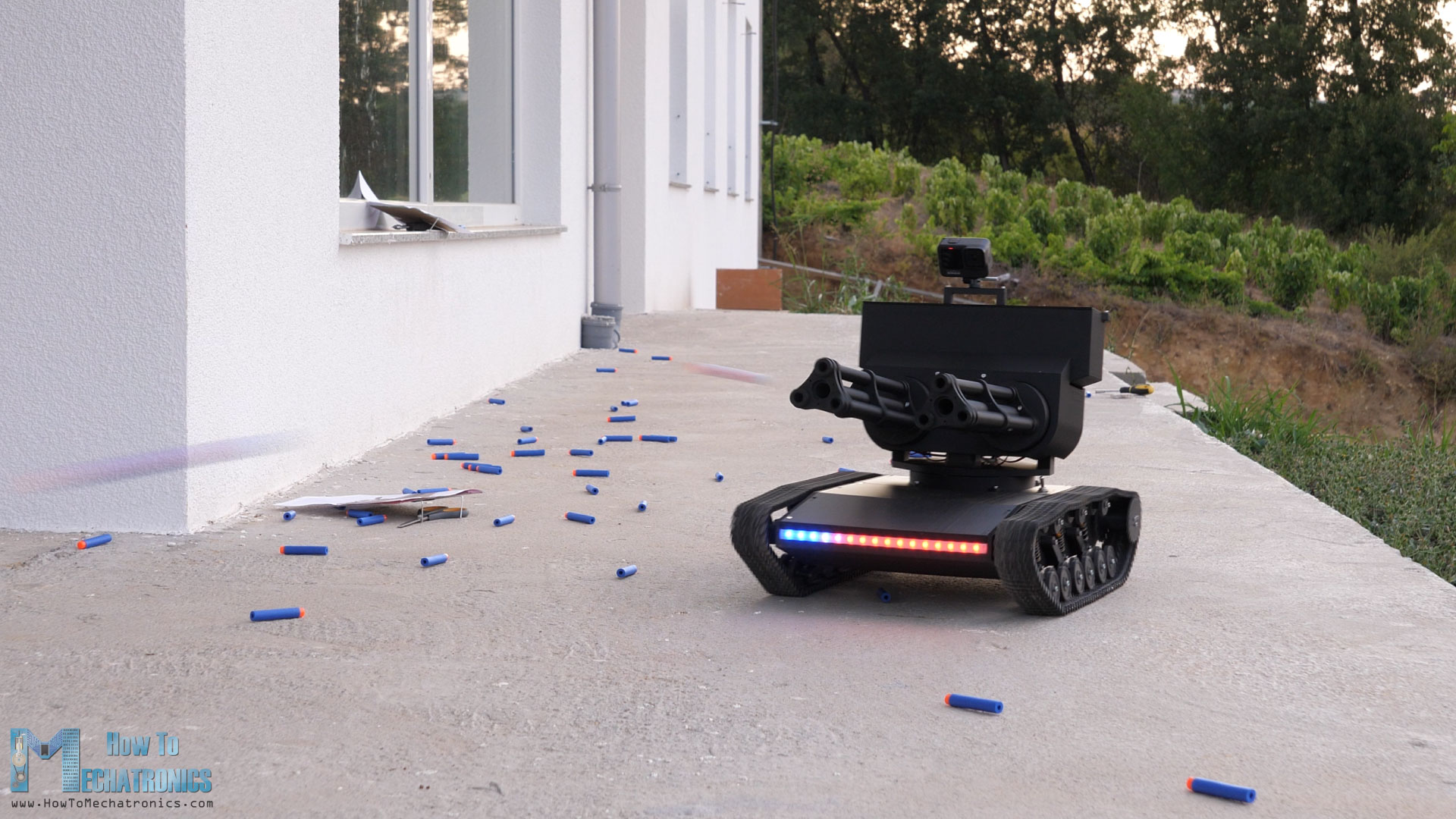
These are the maximum stats, which aren’t something crazy, but we can control them independently, both the firing power and the firing rate, through the RC transmitter.
For controlling the tank I’m using a cheap commercial RC Transmitter which sends commands to it. At the tank, there is a suitable RC receiver which receives the commands and sends them to a microcontroller.
The brain of this platform is an Atmega2560 microcontroller-based board and for easily connecting everything together I made a custom PCB which can be simply attached on top of the board.
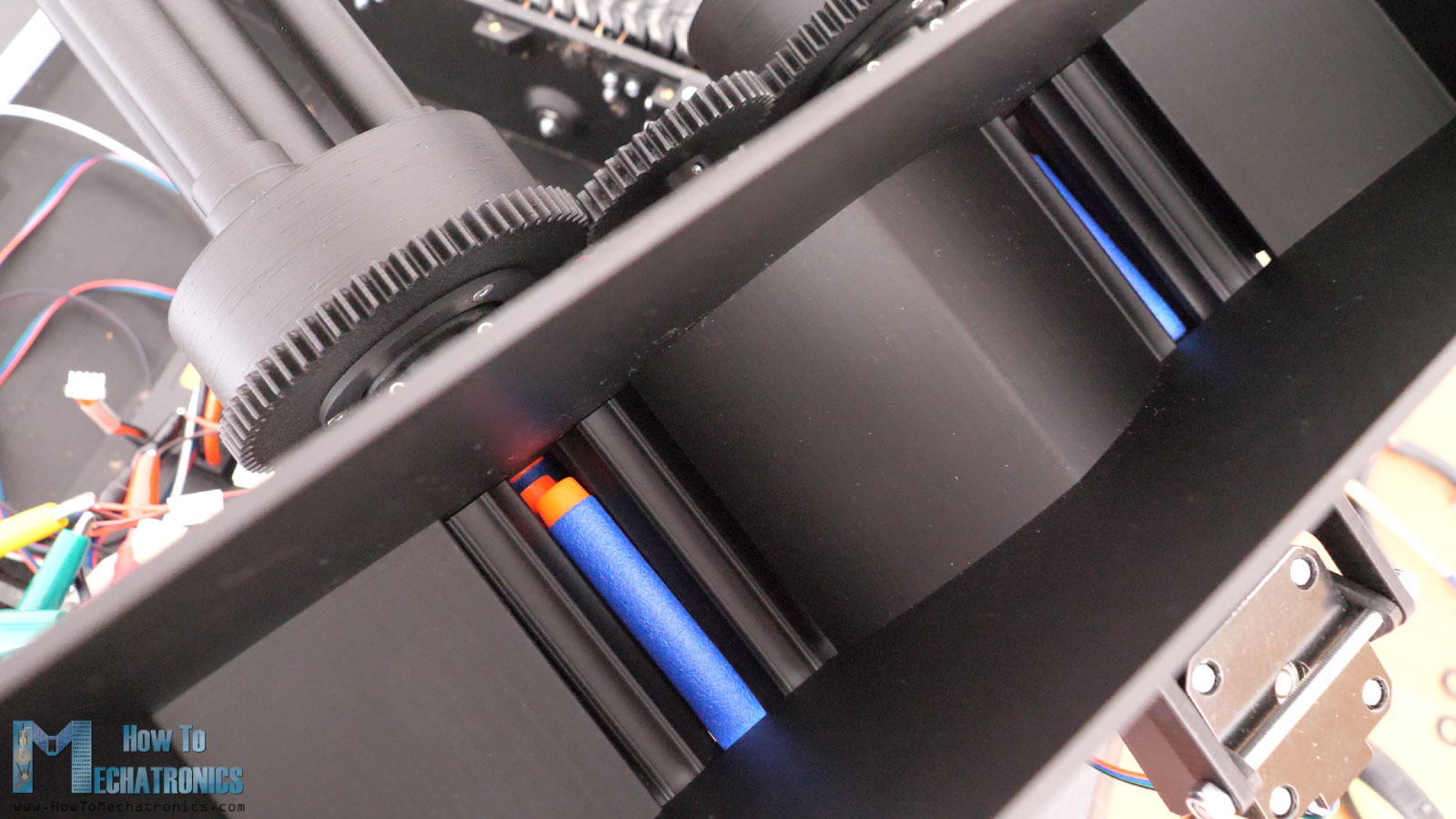
So, as I already mentioned, we don’t have a real minigun or gutling gun mechanism that fires the nerf darts, but a simple and common method of firing nerf darts with the help of flywheels. The flywheels spin at a very high RPM and in opposite direction, so when the soft part of the nerf dart comes in contact with them; they propel the dart quite vigorously.
To get the nerf darts to that propelling position, we have a rotating part that simply pushes the darts in place as it rotates.
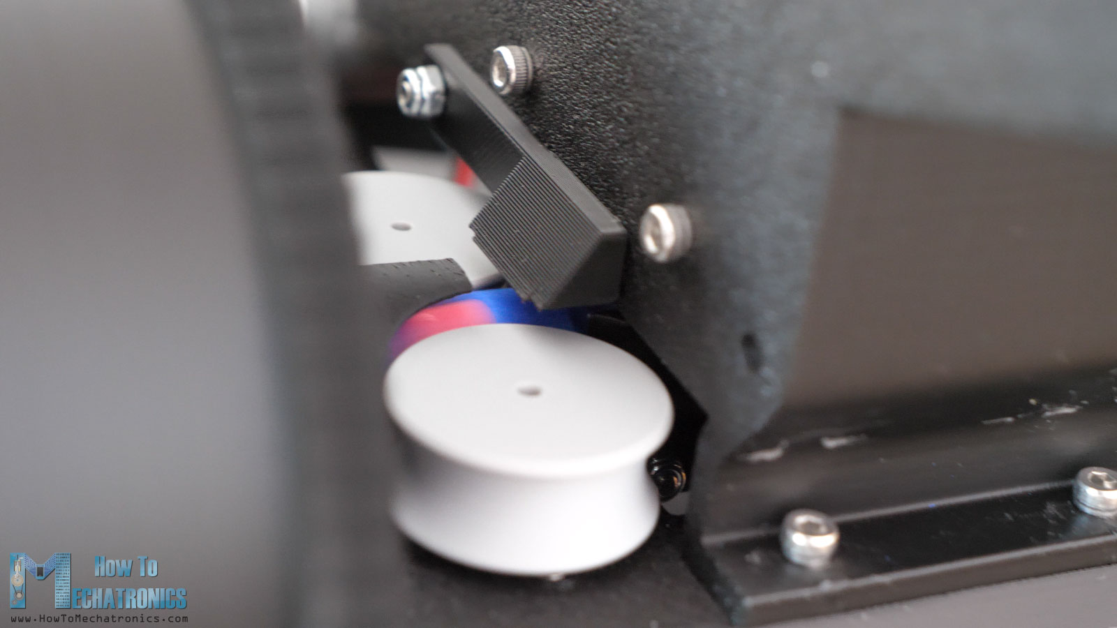
And as for storing the nerf darts, I used yet another simple method. I made a big magazine that holds the nerf darts, and with the help of gravity and the two rollers at the bottom of the magazine, the nerf darts are brought in place for the pusher to push them to the flywheels.
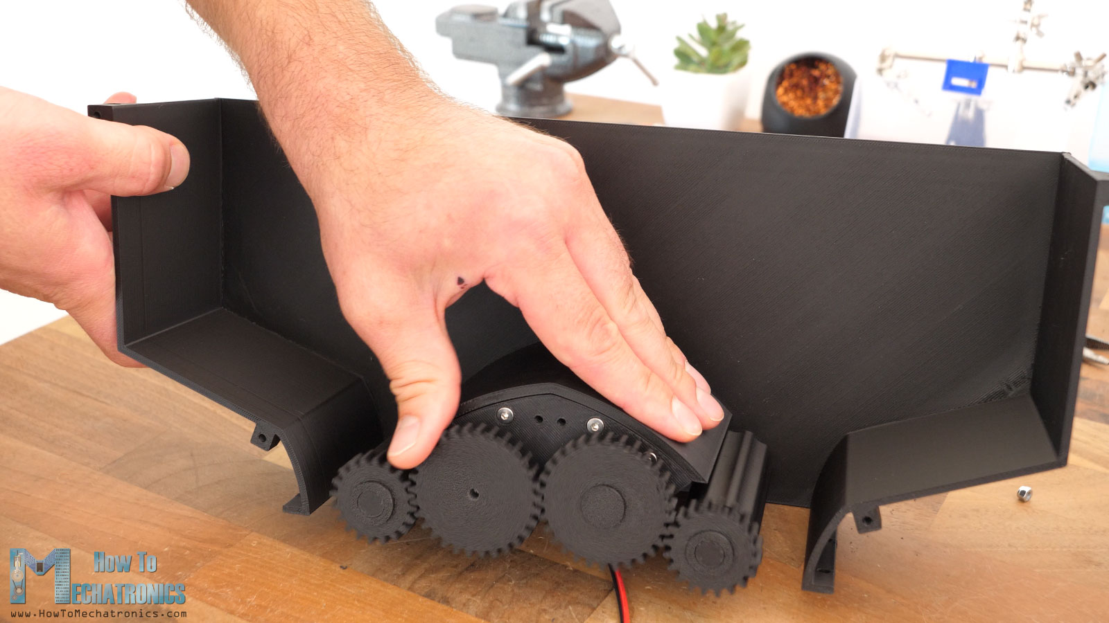
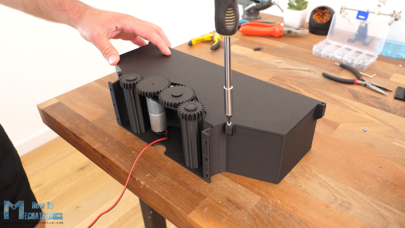
Anyway, few words about the tank from the previous video. So, it’s a fully 3D printed tank that I designed, featuring a dual speed gearbox through which we can select lower or higher gear and get either higher torque or higher speed to suit the terrain or the application that is used for.
The tank also has some cool LED lights, i.e. addressable led strips through which we can create endless stunning light effects. So, for all details about building the tank, you can watch the check the previous article, and now in this article we can focus on building the minigun turret for it.
Designing the NERF Minigun Turret
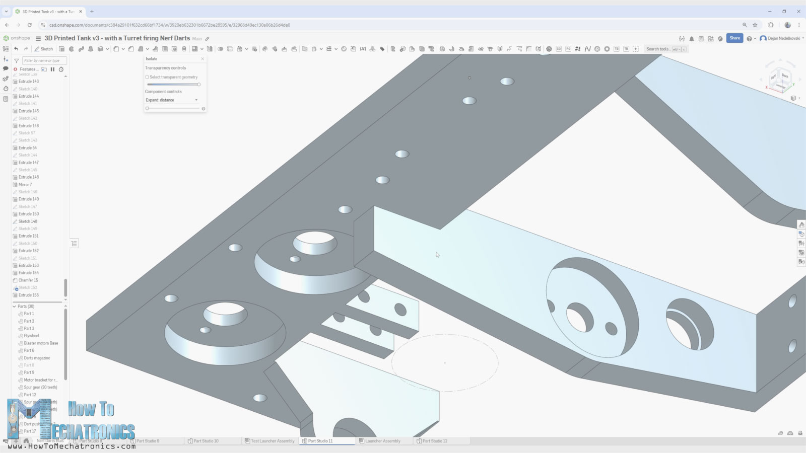
Let’s take a look at the design process first. I used Onshape for designing the turret, which is also the sponsor of this project.
Onshape is the professional grade cloud native 3D CAD & PDM system that I use for my projects.
I recommend that mechanical engineers and product designers check out Onshape, you and your company can use Onshape Professional for free up to 6 months at https://Onshape.pro/HowtoMechatronics
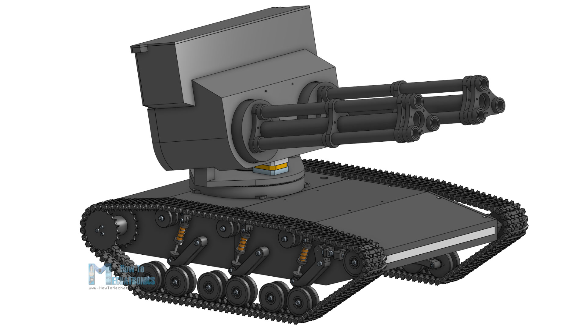
My main goal for this project was to be cool looking honestly, so that’s why I came up with this double barrel design, as well as to have a big magazine to accommodate as much nerf darts as possible.
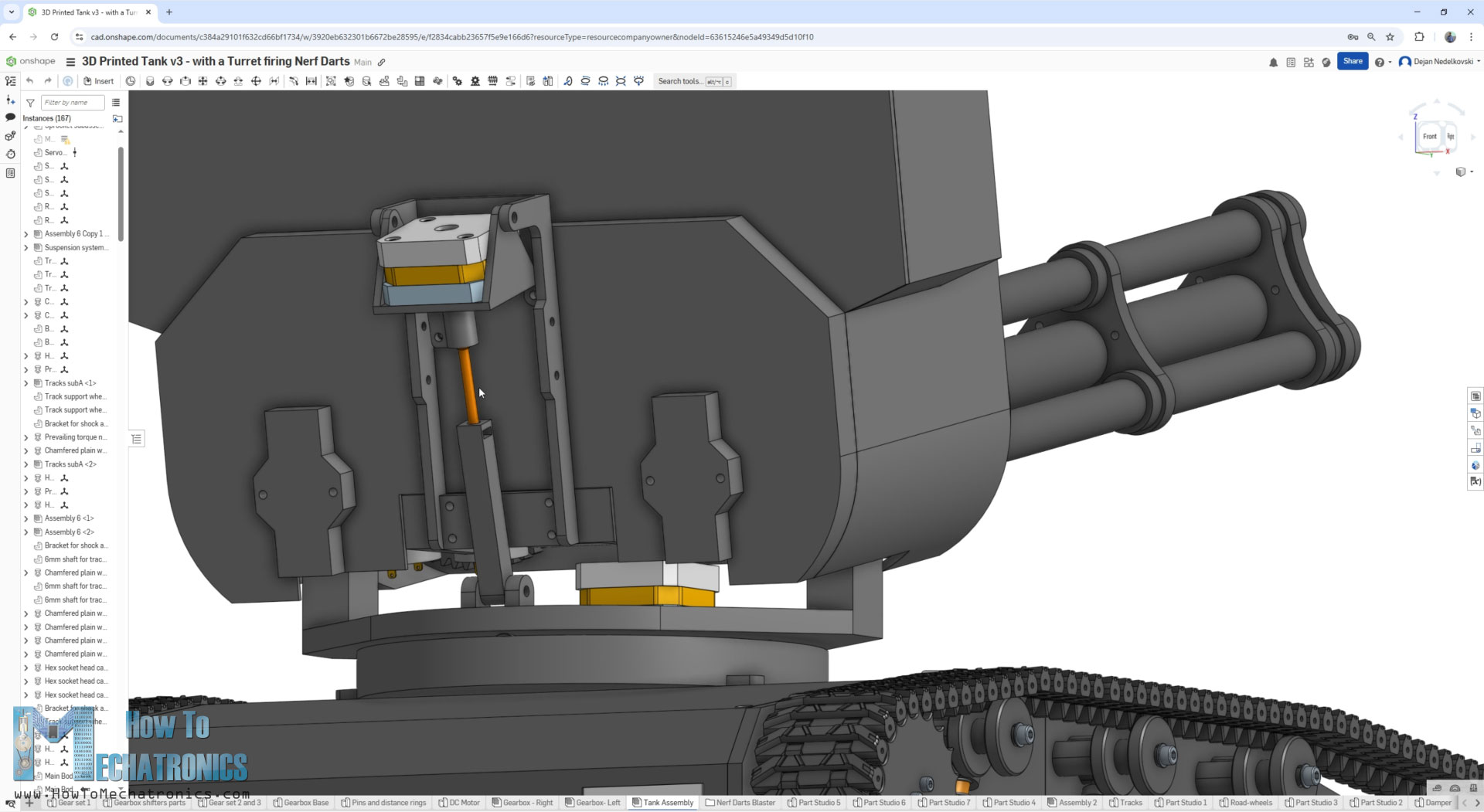
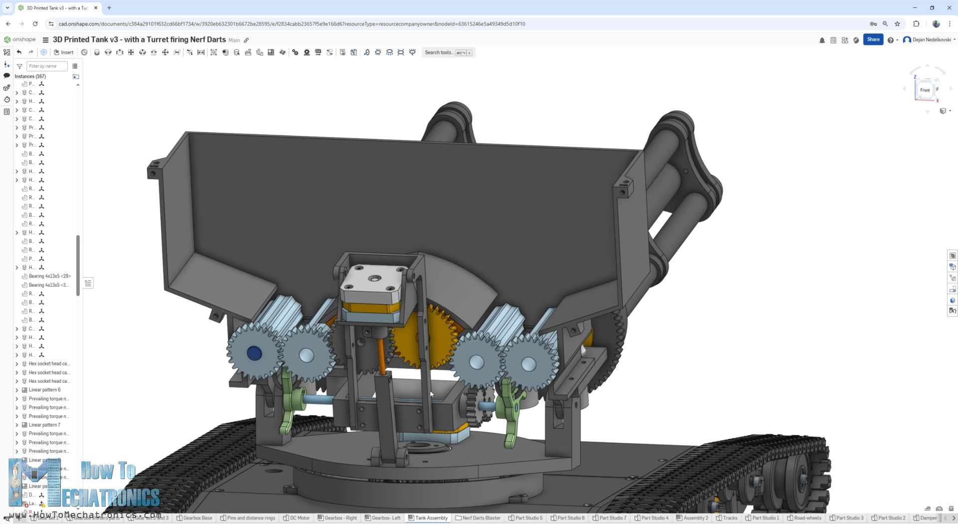
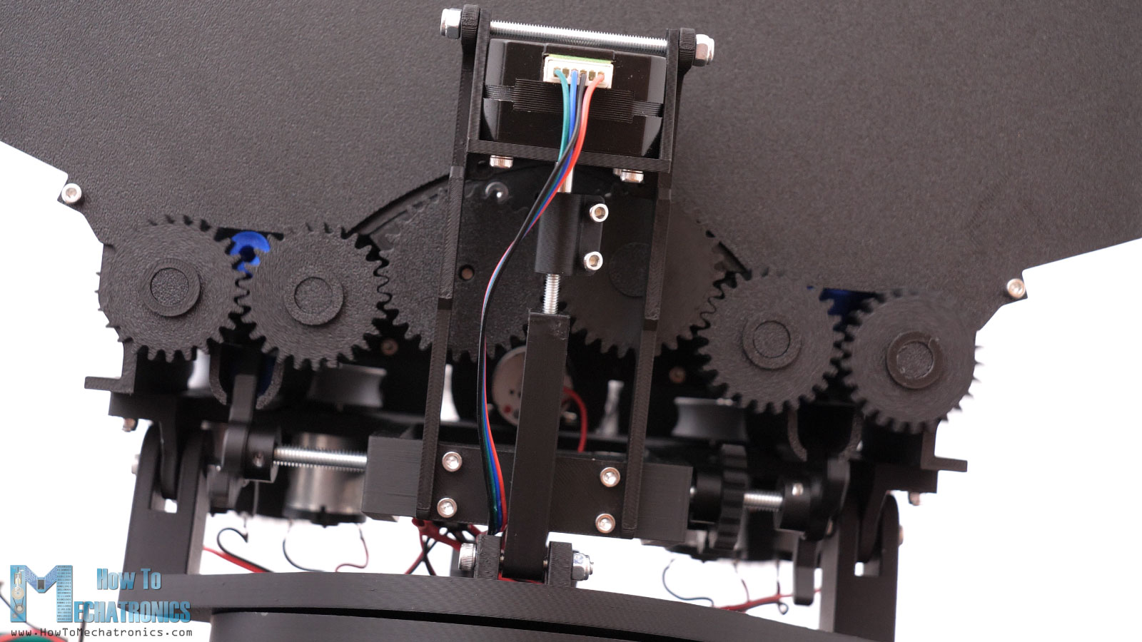
For the pan and tilt movement of the turret, I used two short NEMA17 stepper motors. The pan movement happens at the base with the help one gearset.
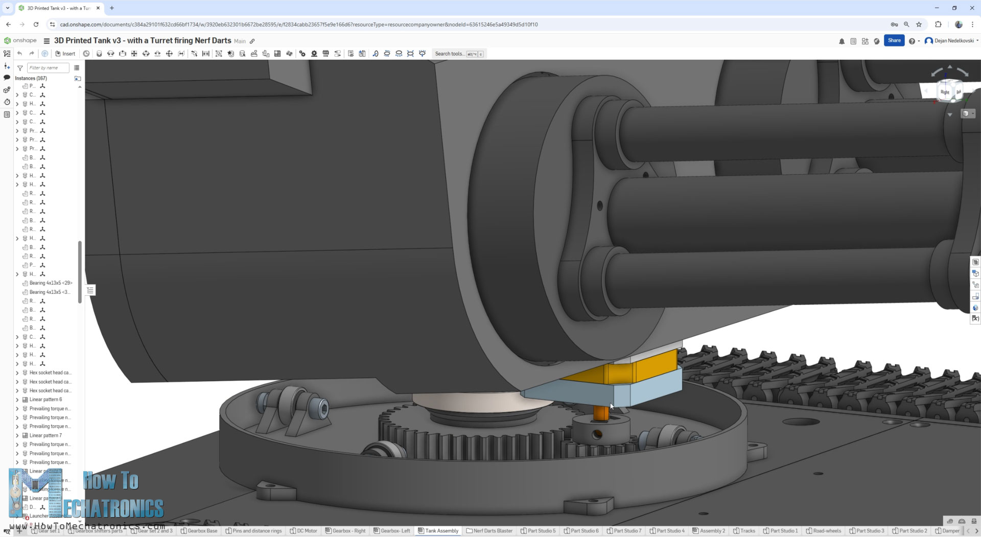
The base is fixed to the tank and has a fixed gear in the center, and the upper part of the turret pans or rotates as the stepper rotates the other pair to the gearset around the fixed central gear.
On the other hand, the tilt movement happens at the back side with the help of a screw drive mechanism.
The flywheels are driven by 12000 rpm DC motors. We need two flywheels for each barrel, so we need total of 4 of these 12V DC motors.
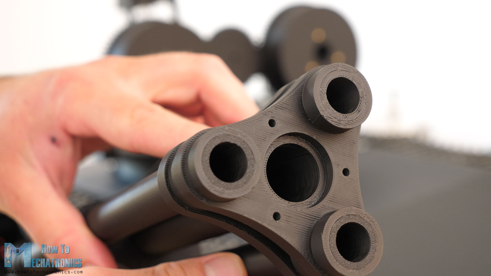
When fired, the nerf darts fly through the central barrel. The other barrels around it are there just to get that cool looking appearance.
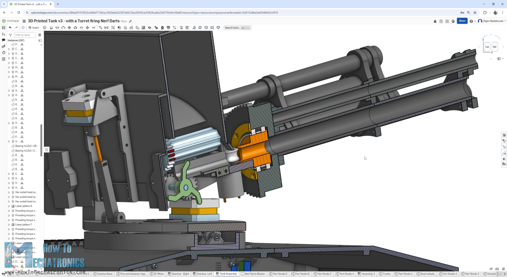
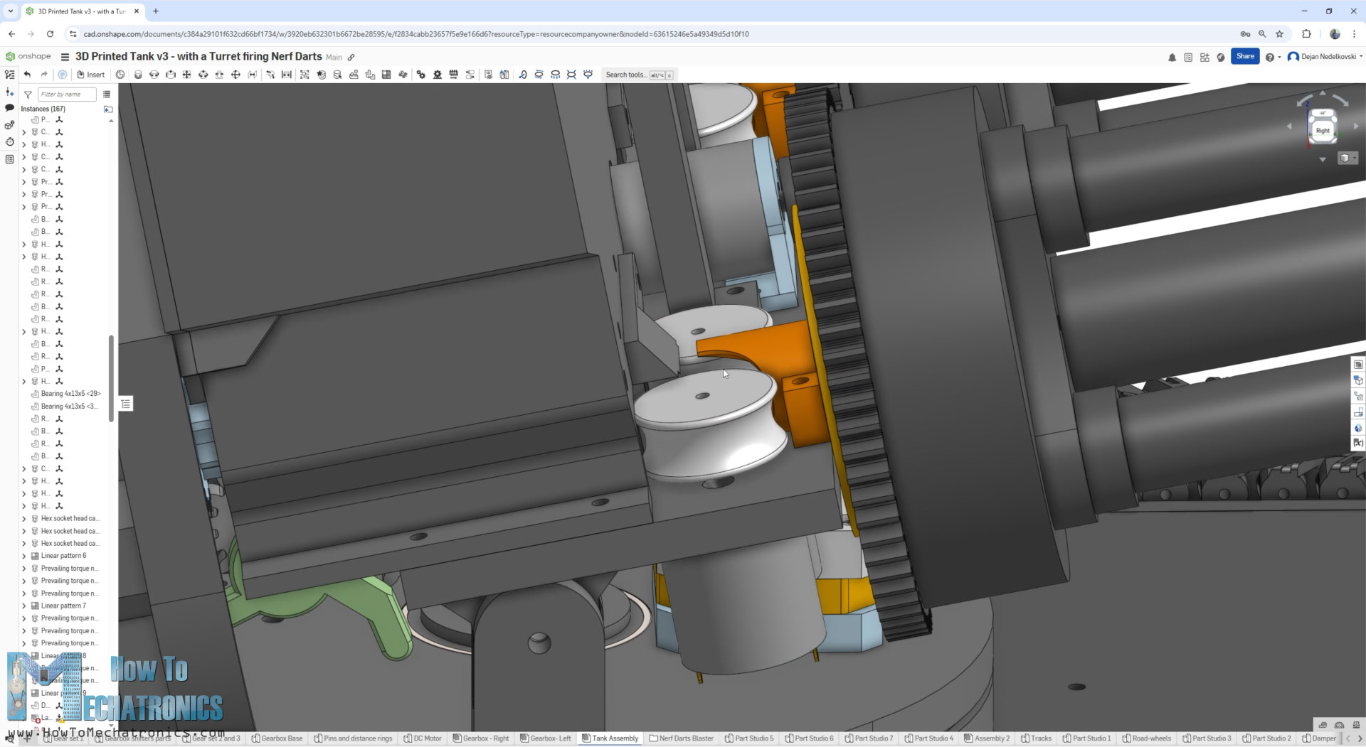
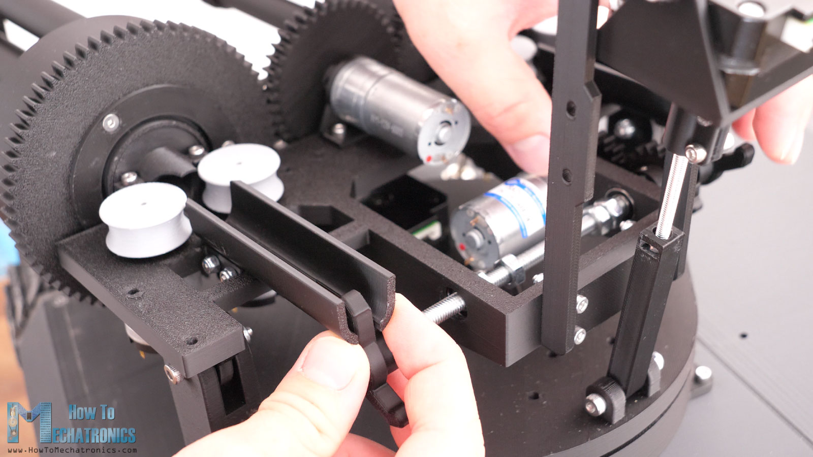
For pushing the darts into the flywheels, I’m using a 50rpm DC motor that drives a 6mm shaft through a gearset. On each side of the shaft, we have these darts pusher part, which pushes the darts into the flywheels as the shaft rotates.
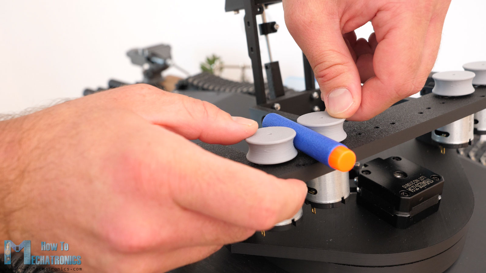
Then we have this magazine that can hold around 200 darts, and at the bottom of it these rollers which help guiding the darts into position to be pushed to the flywheels.
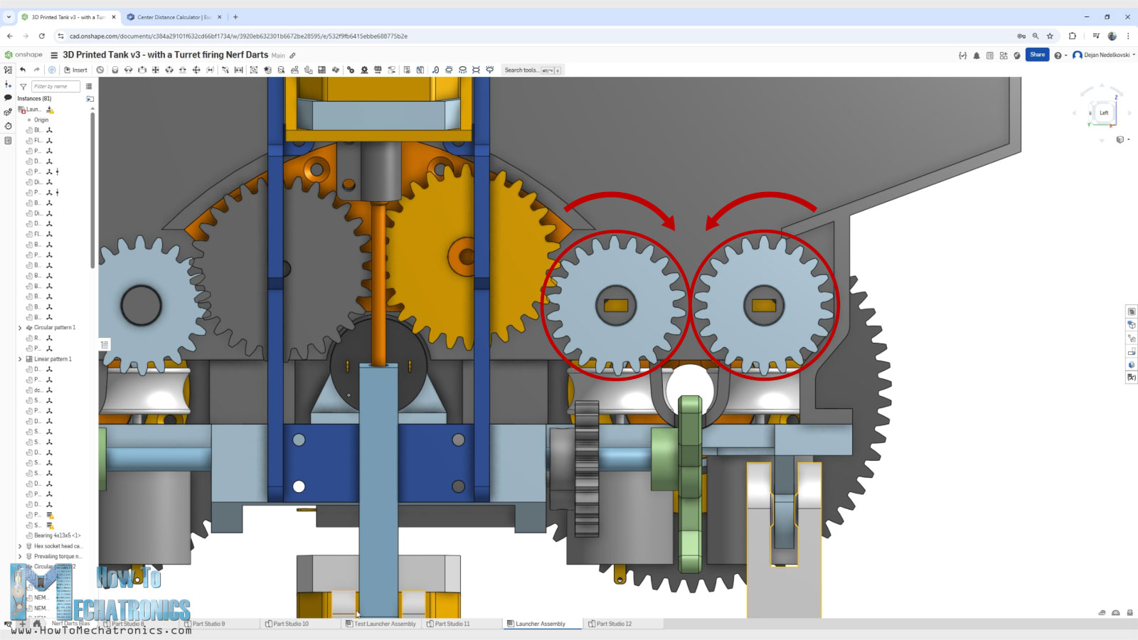
The rollers are driven by a 20rpm DC motor paired with couple of gears to get them rotating in the right direction.
This was actually the most challenging part of the entire project. I mean, at first sight, it looks simple. Under the gravity the darts should go down, and the rollers guide them, but the problem is that the nerf darts are very light weight. In addition to that, they are nose-heavy because of the front rubber tip and that makes them so hard to be guided in this way.
3D Model and STL Download Files
You can view the 3D model of this NERF Minigun Turret RC tank directly on your web-browser with Onshape.
You can get the 3D model of this RC tank/ robot platform , as well as the STL files for 3D Printing from Cults3D.
3D Printing
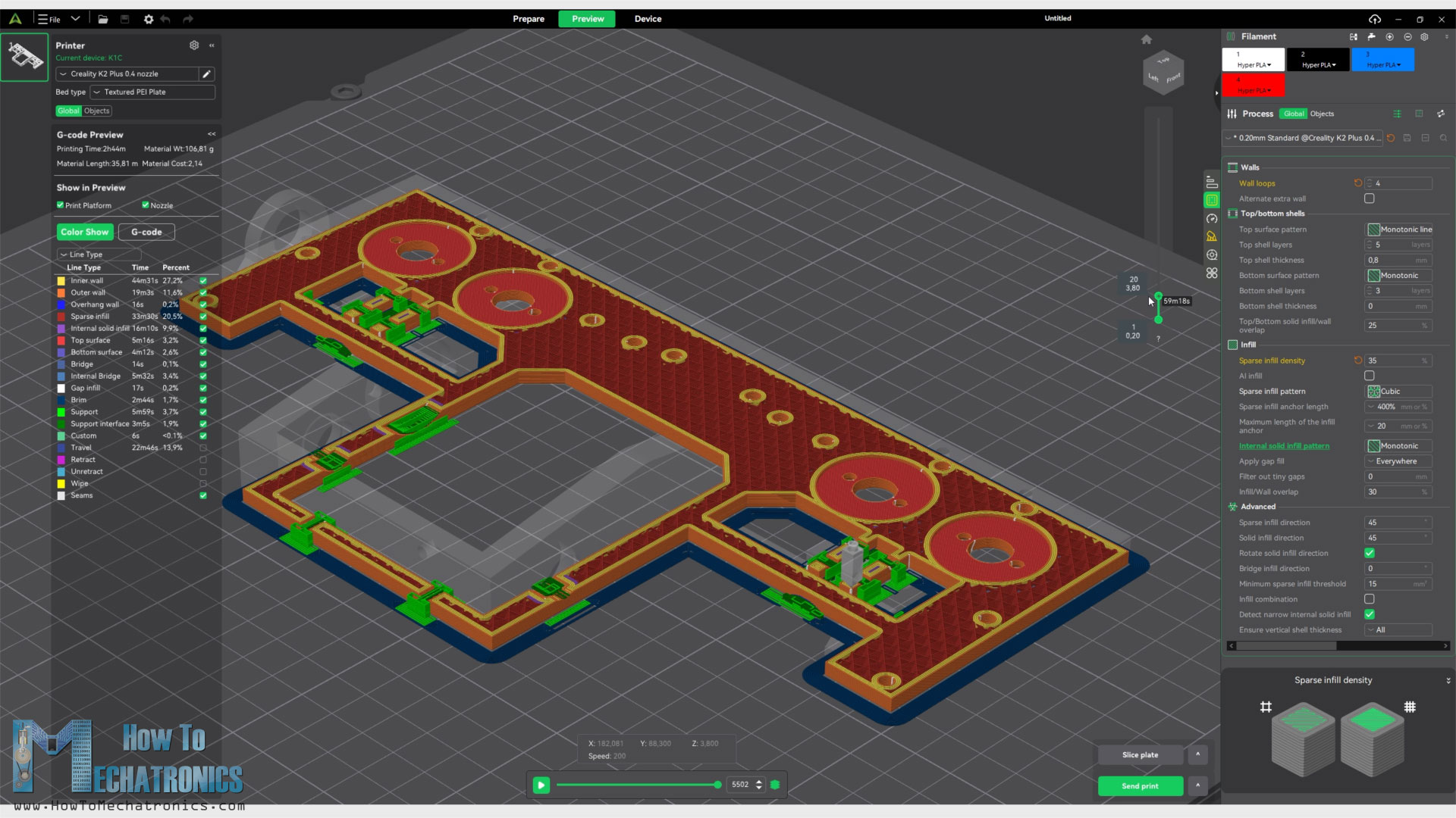
I always say this in my videos, when 3D printing, it’s essential to use the Horizonal Expansion feature, or now in the Creality Print slicer, it’s called X-Y contour compensation and X-Y hole compensation.
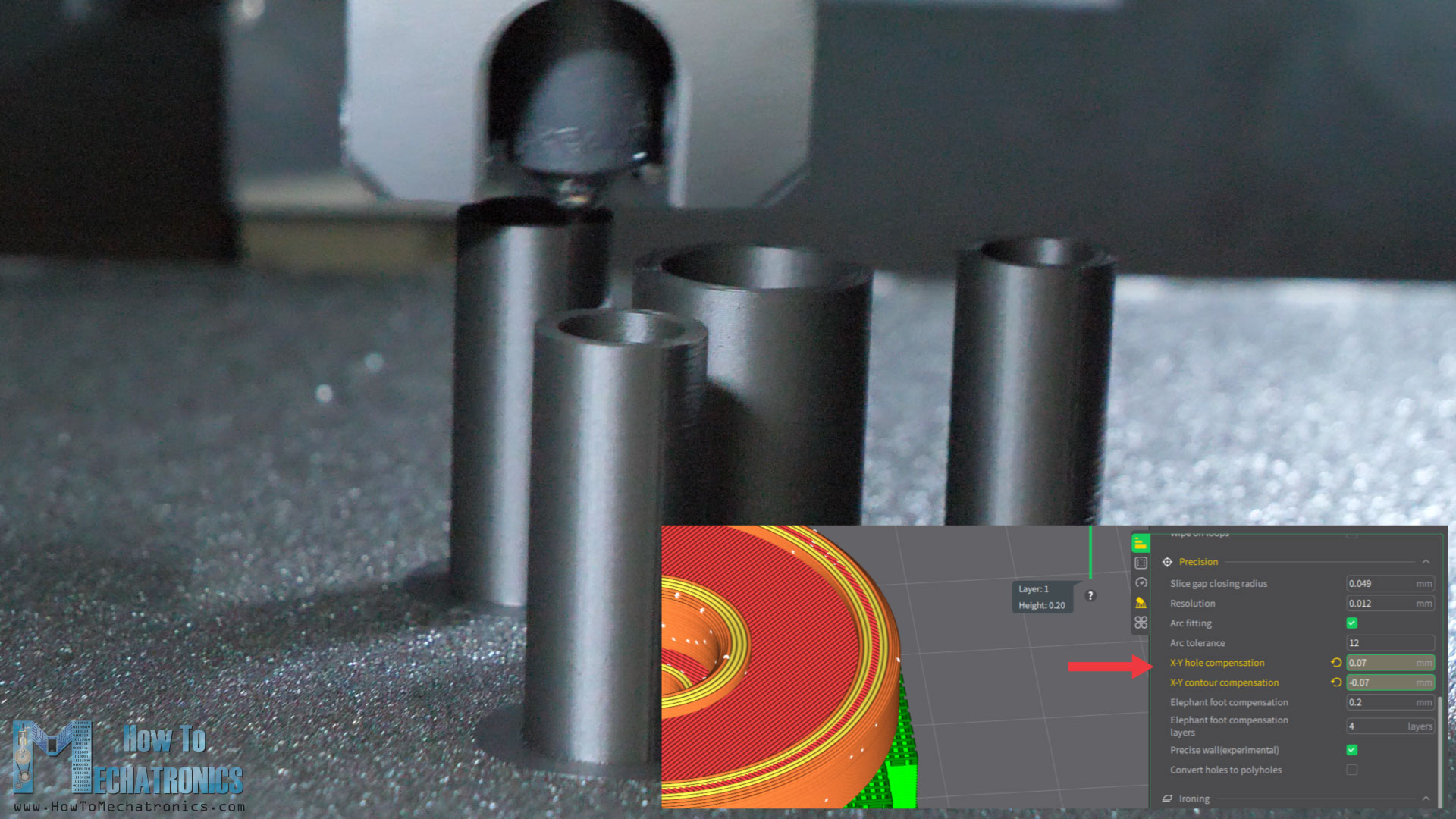
If we leave these settings by default, the prints dimensions probably won’t come out exactly the same as in the CAD model and that’s due to the expansion of the filament when 3D printing. The holes usually come out smaller, and the contours bigger.
For this project, for some of the parts, like for example the magazine rollers and their shafts, we need loose joints or clearance fit, and on the other hand, for some parts, like the barrel’s assembly, we need tight joints or interference fit. So, we either use negative or positive values for these settings depending on the part. I used values within a range of +-0.1mm. Though, you can only get these values right by doing some test prints with different values.
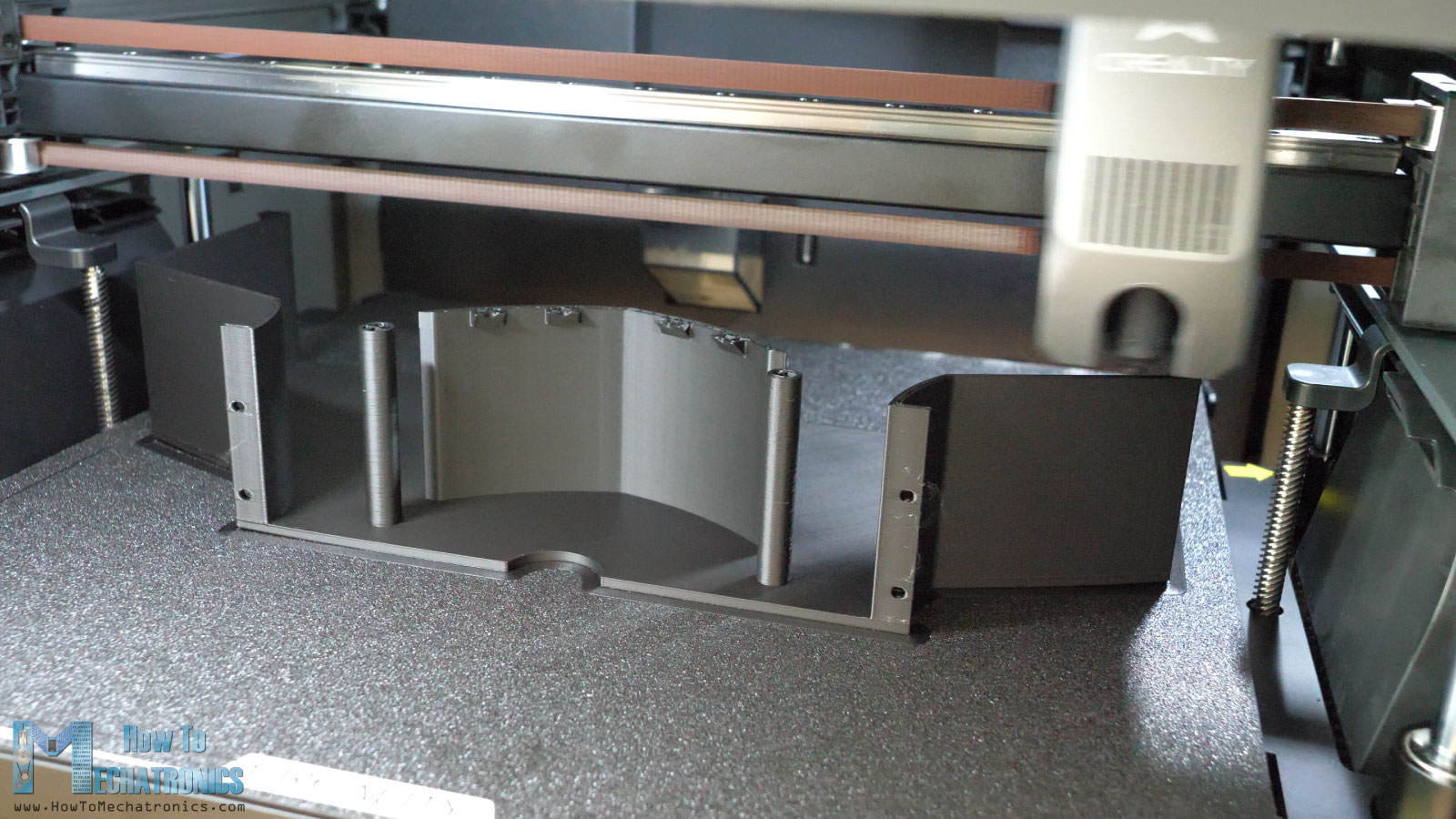
I used the Creality K2 Plus 3D printer for printing all of the parts. Shout-out to Creality for providing me this excellent 3D printer. The Creality K2 Plus is actually one of the best 3D printers I have ever used. You can simply throw anything at it, whether it’s a small part or as big as 350x350mm, and it will get the job done perfectly.
Check my detailed review of the Creality K2 Plus. Also, check it out at: Creality USA store ; Creality EU store ; Amazon.
Assembling the NERF Minigun Turret
All right, so here are all of the 3D printed parts so we can start assembling the turret.
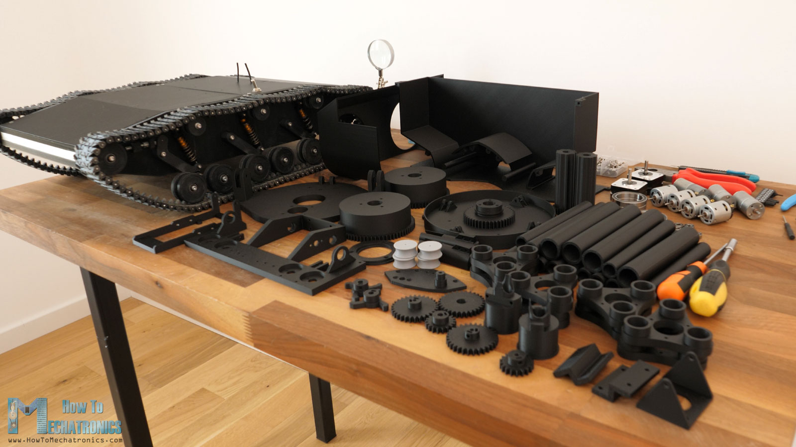
It takes quite some time printing everything as there are many parts and some of them are quite big.
Here is a complete list of components needed for this project, like the DC motors, the bearings and the bolts and nuts.
Bill of Materials
| Electrical Component | Quantity | Purchase Links |
|---|---|---|
| 12000RPM 12V DC Motor RS360 | 4 | Amazon | AliExpress | Temu |
| 300RPM 12V DC Motor – JGA25-370 | 1 | Amazon | AliExpress | Temu |
| 60RPM 12V DC Motor – JGA25-370 | 1 | Amazon | AliExpress | Temu |
| 30RPM 12V DC Motor – JGA25-370 | 1 | Amazon | AliExpress | Temu |
| NEMA17 30mm Stepper Motor | 2 | Amazon | AliExpress | Temu |
| Wires ~20AWG | ~3m | Amazon | AliExpress | Temu |
| Mechanical Component | Quantity | Purchase Links |
|---|---|---|
| RC Shock Absorbers | 8 | Amazon | AliExpress | Temu |
| Ball Bearing 686 – 6x13x5mm | 2 | Amazon | AliExpress | Temu |
| Ball Bearings 624 – 4x13x5mm | 44 | Amazon | AliExpress | Temu |
| M6 Threaded Rod | 200mm | Amazon | AliExpress | Temu |
| M3 Threaded Inserts | ~30 | Amazon | AliExpress | Temu |
| M3 Grub Screw | ~10 | Amazon | AliExpress | Temu |
| M3 and M4 bolts and nuts | To be specified | Amazon | AliExpress | Temu |
| Bolts | Nuts |
|---|---|
| M2.5×6/8 countersunk – 8 M3x8mm – 14 M3x10mm – 10 M3x16mm – 12 M3x16/18mm – 4 M3x20mm – 10 M3x25mm – 4 M3x8mm countersunk – 12 M3x10mm countersunk – 4 M4x20mm – 6 M4x25mm – 2 M4x30mm – 1 M3 Grub screws – 10 | M3 Lock-nut – 50 M3 nut – 10 M4 Lock-nut – 40 M4 nut – 1 M6 nut – 4 |
Disclosure: These are affiliate links. As an Amazon Associate I earn from qualifying purchases.
For the electronic bill of materials, please check the circuit diagram section.
Assembling the turret
Actually, before assembling the turret, I installed new springs to the shock absorbers. This is a must-do step because now with turret we will add quite a mass to the top of the tank.
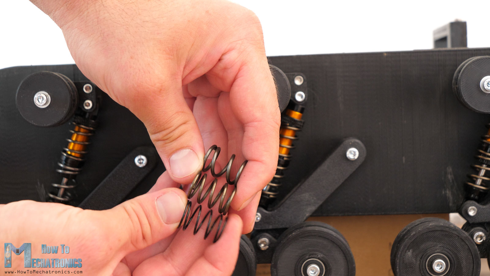
The original springs of the shock absorbers are just too weak and won’t be able to hold up all that weight. I bought springs with the same dimension as the original, 30mm in length and 15mm outer diameter, just with ticker wire. The original wire was 1mm tick, here I could easily press that spring with two fingers. The new ones were 1.5mm tick and were much stronger. At the back side I installed a 1.8mm spring because most of the weight of the turret will be back there. Though, I would recommend you to get just the the1.5mm springs as they would be strong enough even for the back.
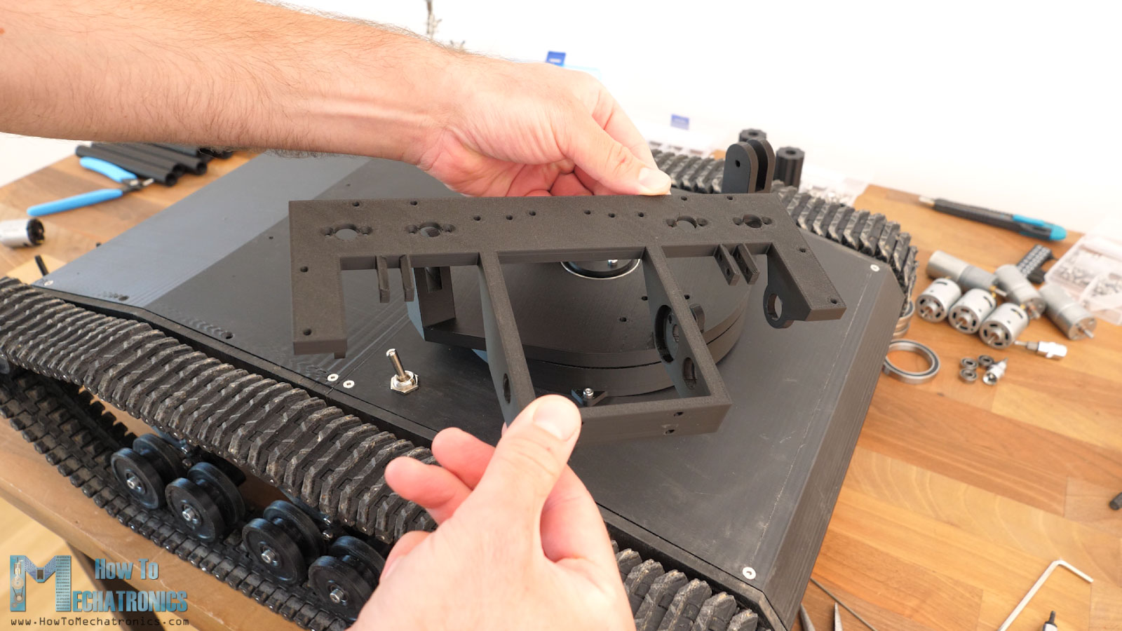
Anyway, we can start the assembling with installing the base of the turret in place. This base part will be fixed to the back side of the tank cover. The are two holes on the inside of the base that match with two holes on the tank cover, and I used them to align the base properly, and when using a 3mm drill made holes to the tank back cover.
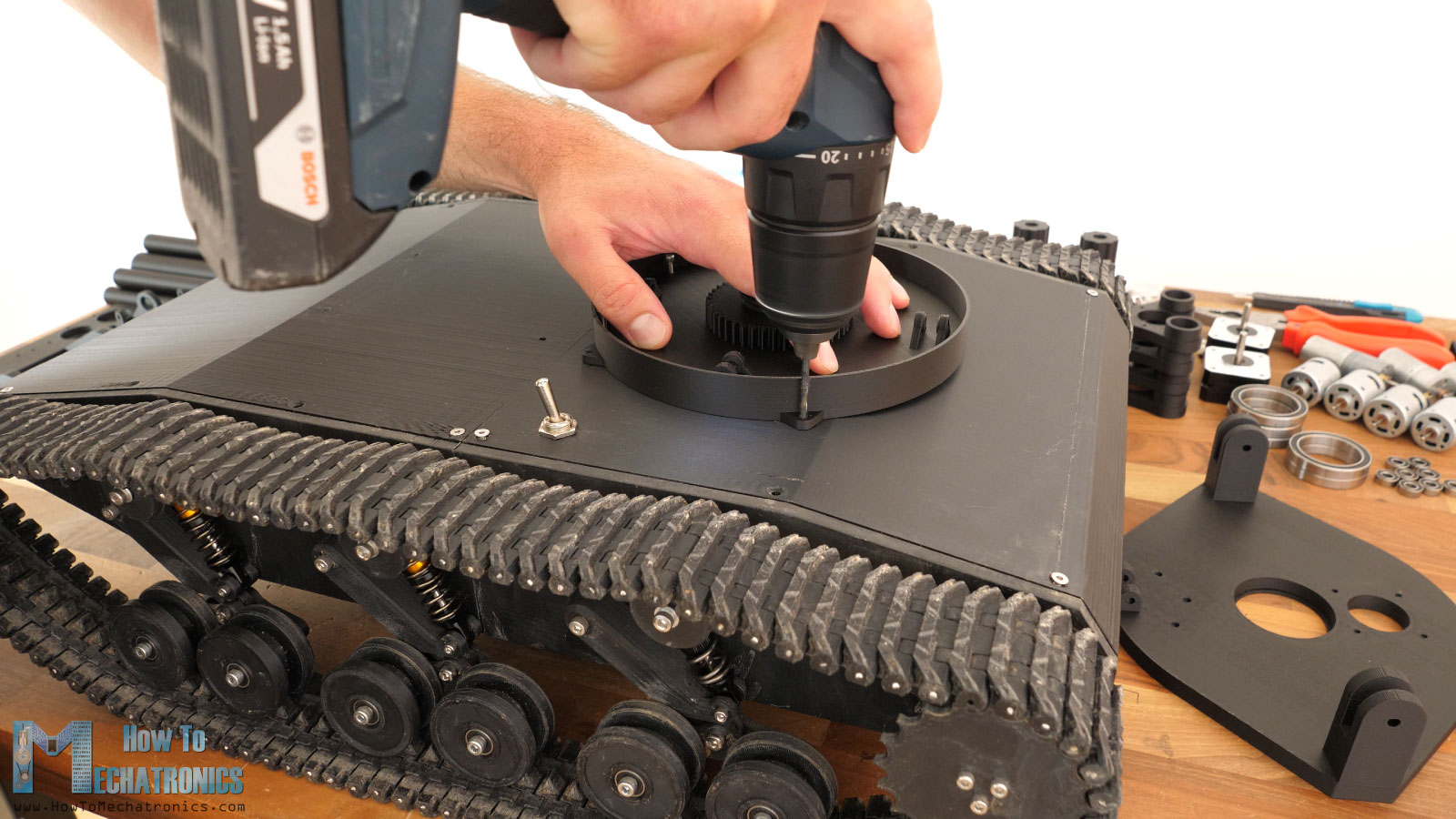
I specifically placed these holes to be on the ribs on the inside of the cover, so they will be strong enough to hold the turret base securely. I also marked and made a hole for the wires from the turret to pass through. I mean, these new holes will be updated to the original tank 3D model files, so if you are building the tank now the holes will be there. We secure the turret base to the tank cover with using four M3 bolts and nuts.
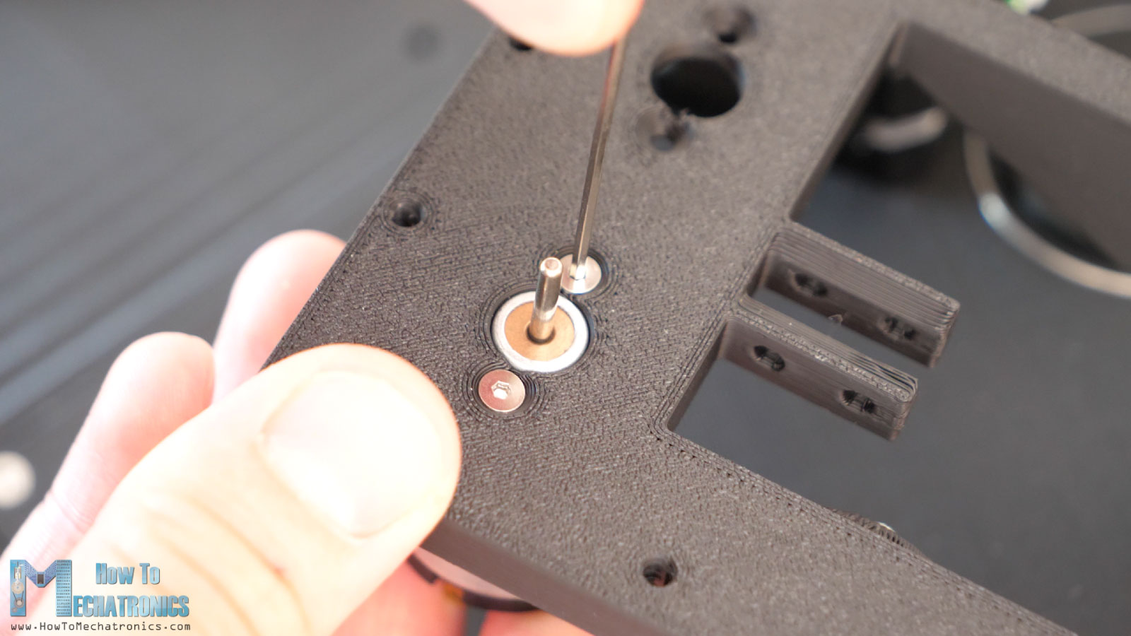
Next, we can install the panning platform on top of the base. This platform sits and rotates on top of some ball bearings attached to the base. I’m using 13mm outer diameter bearings with 6mm inner diameter.
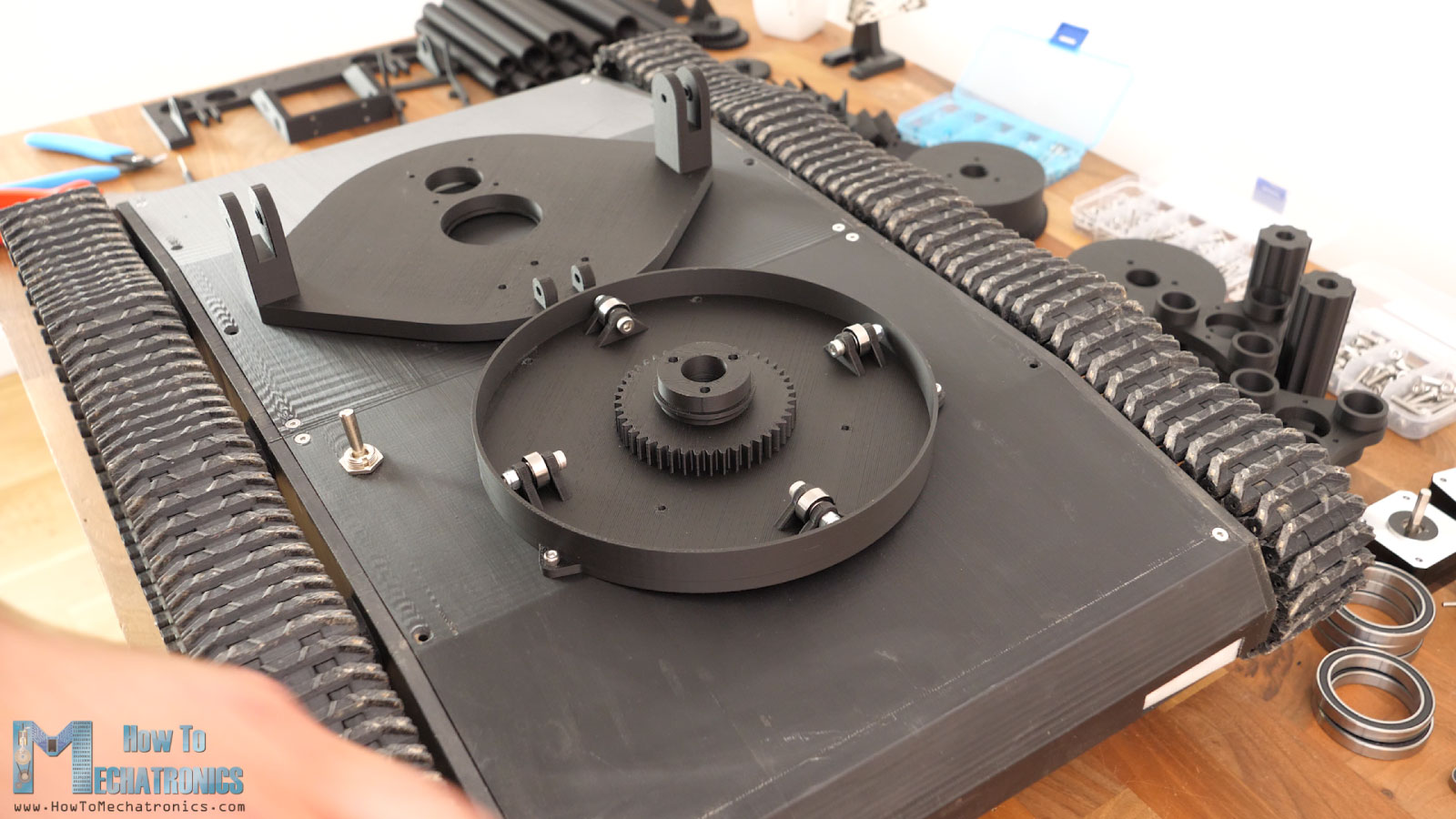
My intention was to use the bearings with 4mm inner diameter, but I ran out of them, so 3d printed some sleeves so I can still use these bearings with 6mm inner diameter and M4 bolts. You see I installed 4 of these bearings, but I will upgrade the model to be with 6 bearings to have better contact.
To keep the two parts aligned, we are using a bearing with 47mm outer and 35mm inner diameter. The bearing fit in-between both parts and so we get nice and smooth motion. For securing the upper part we will use this flange on top of bearing. Though, before we do that, first we need to insert the stepper motor for the panning. The stepper is a NEMA17 but with just 24mm length so it can fit in place.
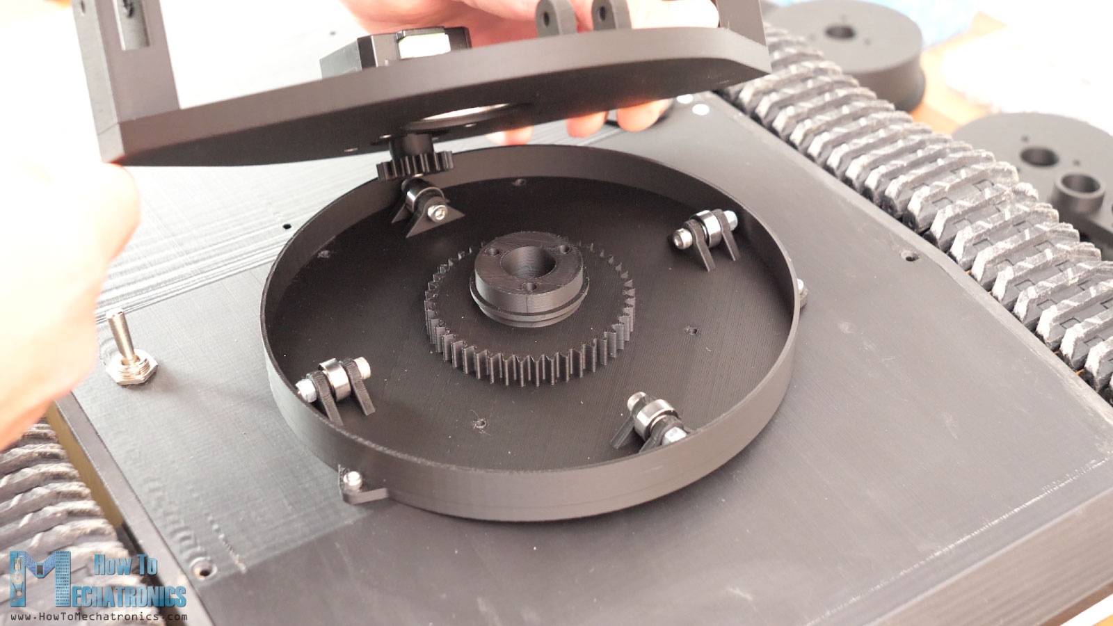
Maybe we could also go with 30mm NEMA17 because I later found that this shorter one was struggling a bit in terms of power with the pan movement. At this point we also need to attach the gear to the motor shaft. For securing it in place, there is a slot for inserting an M3 bolt, and then using a grub screw we can firmly secure the gear to the shaft.
To finish the pan assembly, we need to install some threaded inserts into the base, and then using the flange secure the bearing and with that the panning platform is secured in place.
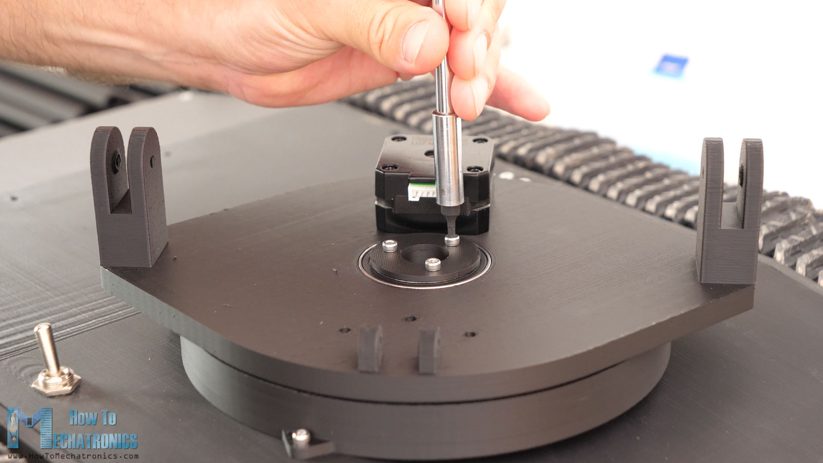
All right, next we can install the tilt platform. That’s this weird looking part which is like Swiss cheese. Yeah, it has so many holes because we need to attach many parts to it.
For the tilt joint we need to install two bearings in on the sides of the platform. These are the same 13mm outer diameter bearings. It’s worth noting here though that we should not force insert the bearings in the holes, because the part here is only 5mm in width and could easily delayer or brake at this location.
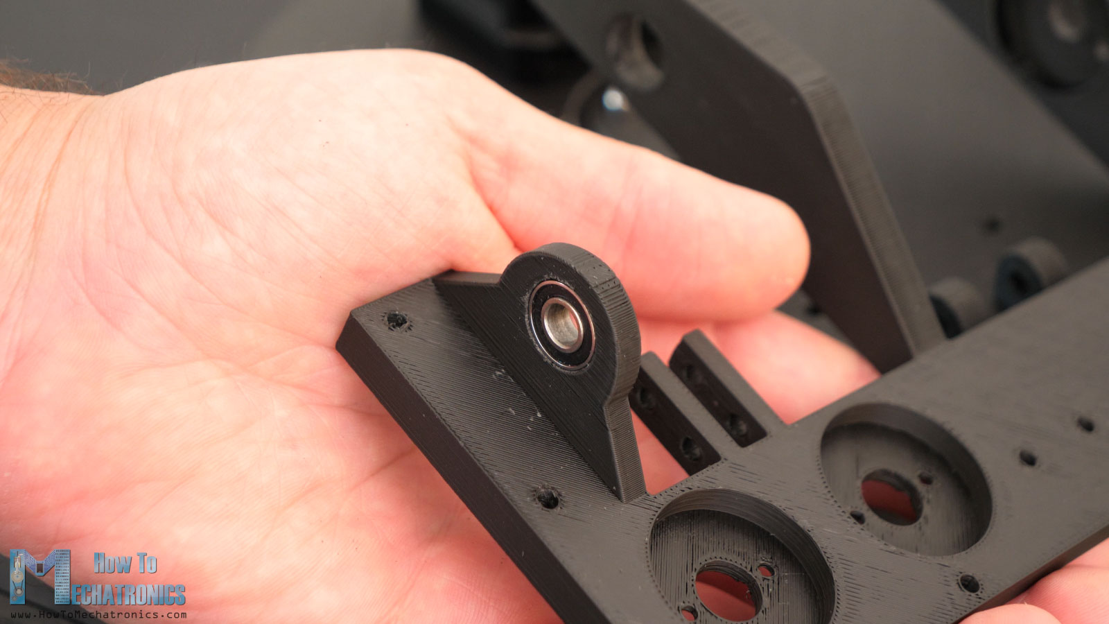
I used a diamond file to smooth and expand the hole so that the bearing can fit in easily. Using two M4 bolts we secure the tilt platform in place and so form the tilt joint.
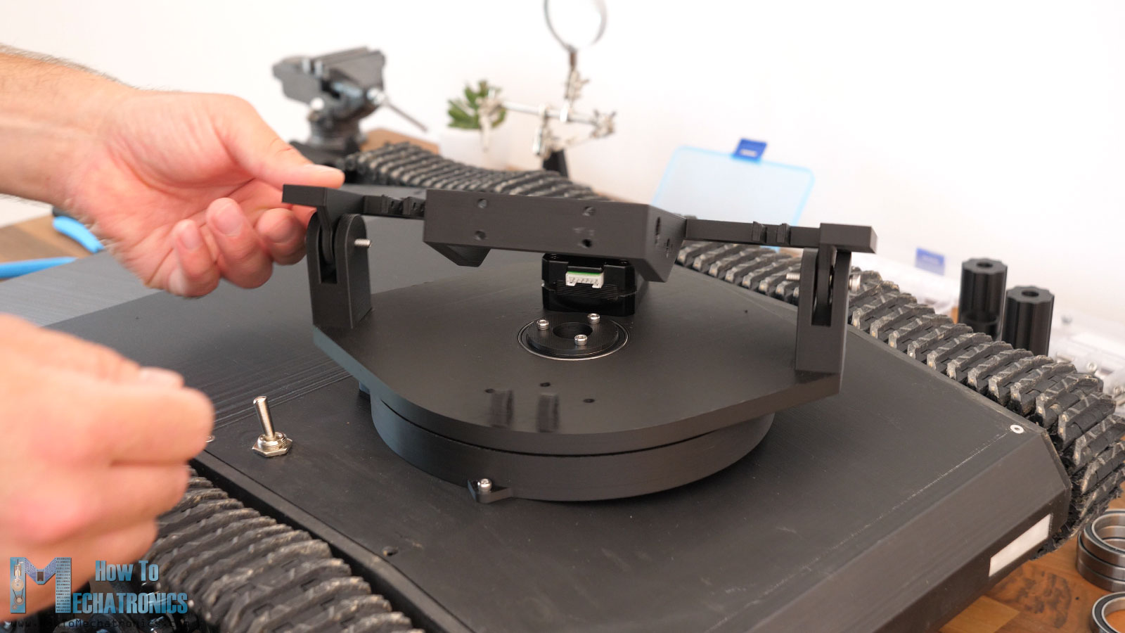
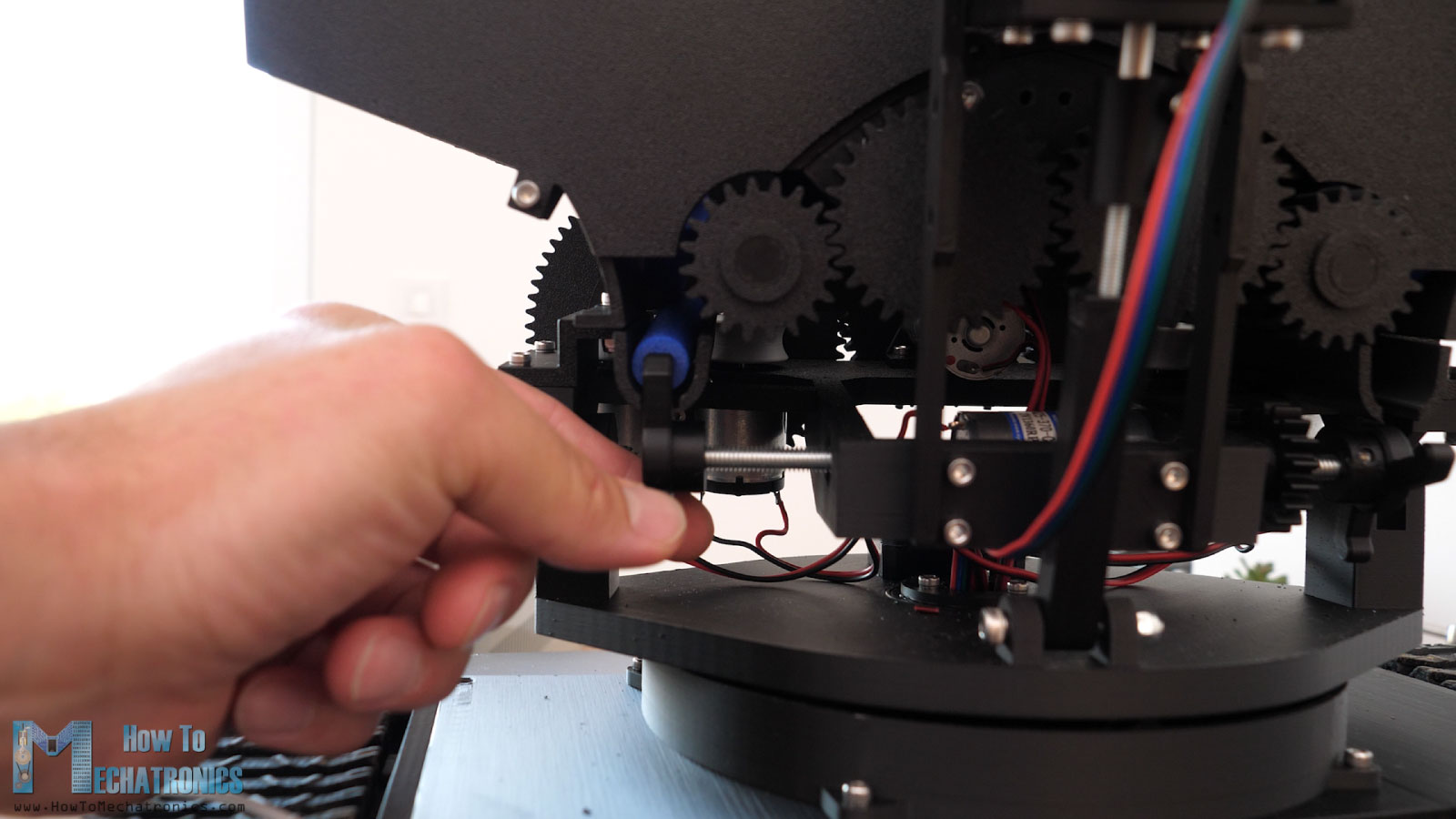
Next, we can install the bracket that will hold the tilt stepper motor. Then we can install the cylinder like part that will form the drive screw mechanism for the tilt movement. We also need an M4 threaded rod for that purpose. We need two pieces of 66mm length.
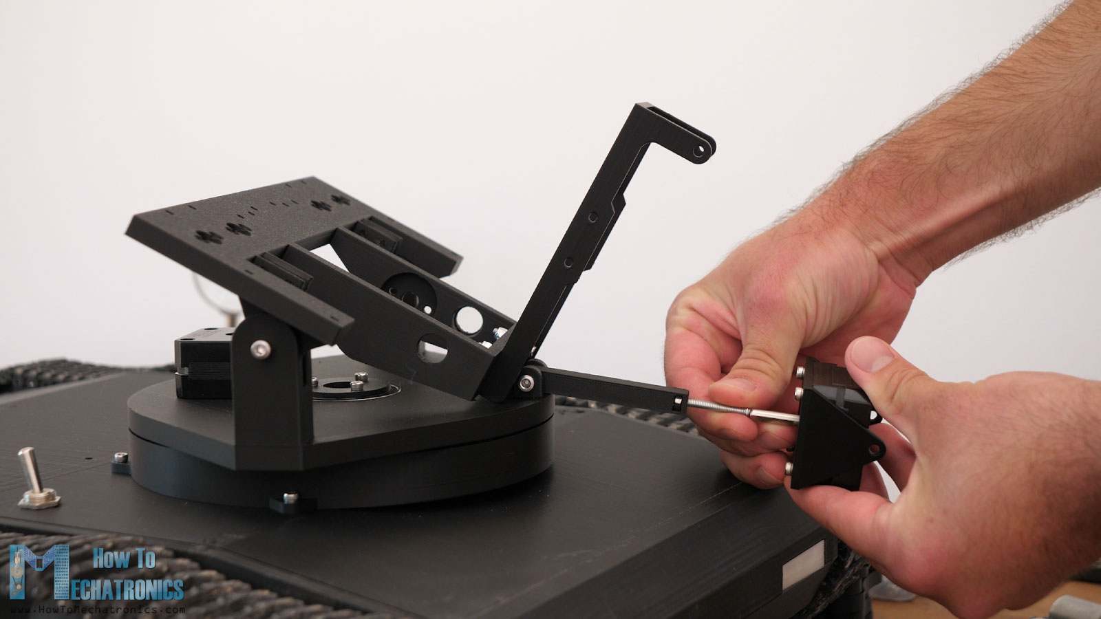
So, first goes an M4 nut at the top of the cylinder part, and then we can screw in the threaded rod. For connecting the 5mm stepper motor shaft to the 4mm threaded rod, I will use this 3D printed coupler which can be tighten with an M3 bolt and nut. Then using the other 66mm rod we just have to connect the stepper brackets and so form the tilt mechanism.
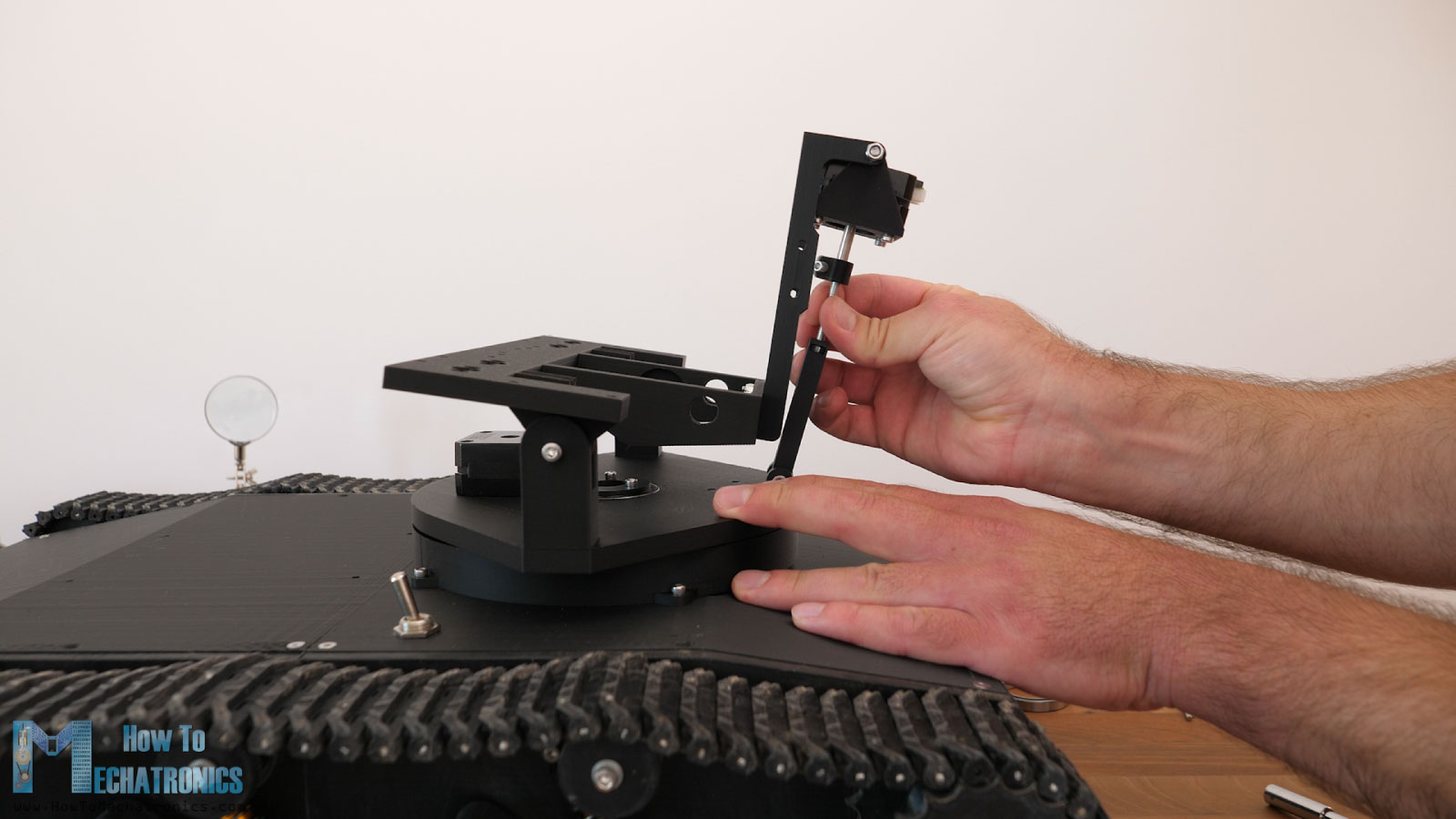
So, as we rotate the threaded rod, the tilt mechanism goes either up or down. We can notice here that the mechanism is not sturdy at all. The wobble comes from the M4 nut which is not tight fit in the cylinder part. I replaced the cylinder to have tighter fit and now it was better. Of course, the whole tilt mechanism wobbles a little bit, because the M4 nut and threaded rod have a play between them, as well as the other joints, but it’s good enough, I think.
Next, we can move on with installing the flywheels DC motors. These are 12000rpm 12V DC motors. We need M2.5 countersunk bolts to secure them in place.
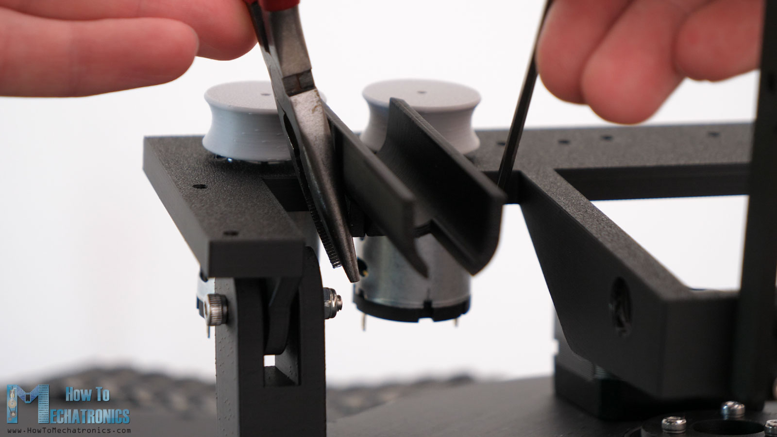
Once secured, we can insert the flywheels to the motor’s shafts. The hole of the flywheel is dimensioned and 3D printed with tolerances to make an interference fit with the motor shaft, so we don’t have to use any screws for securing them in place.
There should be 2.5mm gap between the flywheels and the tilt platform, so here I’m using a 2.5mm drill as a limiter when inserting the flywheels. Though, I later noticed that the shaft of the motor has an axial play of around 0.5mm when pressed, so with the 2.5mm drill as a limiter, we get 3mm gap. So, we should use a drill or anything else with 2mm as limiter.
After installing the flywheels, we should check whether they have a good contact with the nerf darts.
They should have good grip, but at the same time they should not be very tight. For getting the right grip you can try different values of the horizontal expansion settings when 3D printing. That’s also the case for getting the right holes dimensions the interference fit with the motor shaft.
Next, we can install the part that holds the nerf darts before they are pushed to the flywheels.
We secure it in place with two M3 bolts and nuts. I think it’s good to have parts like this to be modular or not printed together as a one part with the platform, as in this way we can modify them at any time if needed.
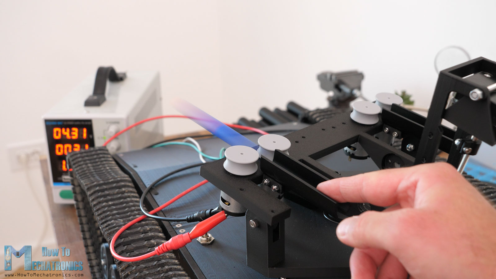
At this point we can connect the flywheels DC motors to power to make sure they work properly before we move in with the assembly.
We will move on with installing the output barrel. This part is designed to fit in-between the flywheels and to guide the nerf darts in the center in case they come out of the flywheels at an angle.
Before securing it to the tilt platform, we need to insert two bearings with 47mm out and 35mm inner diameter, and with distance rings between them. These bearings will hold the rotating barrels of the turret.
Also, we need to add this retaining ring which will later hold the rotating barrels mechanism in place. We secure this output barrel to the tilt mechanism with two M3 bolts and nuts.
Next, we can install the barrel base. This part will rotate through the bearings around the output shaft we just put. For securing it in place first we need to install some threaded inserts to it. Then we can put it onto the bearings.
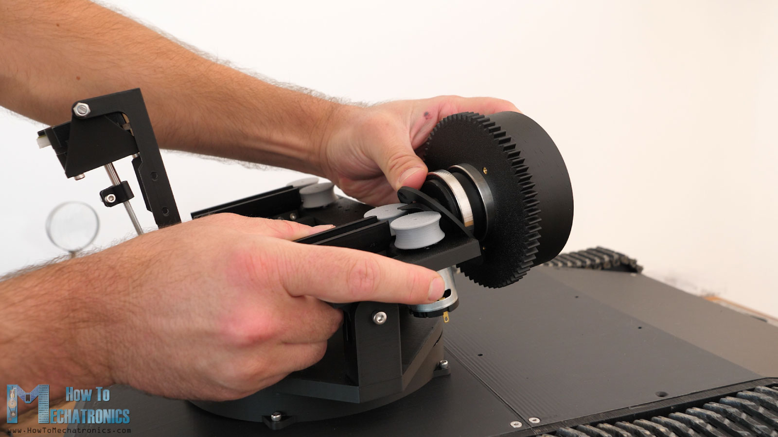
We secure it in place with the retaining ring at the back with the help of some M3 countersunk bolts.
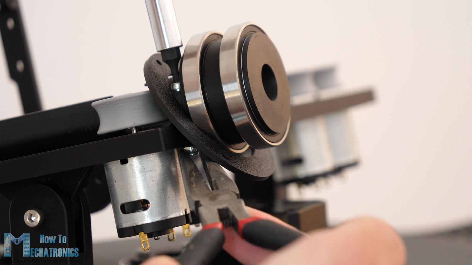
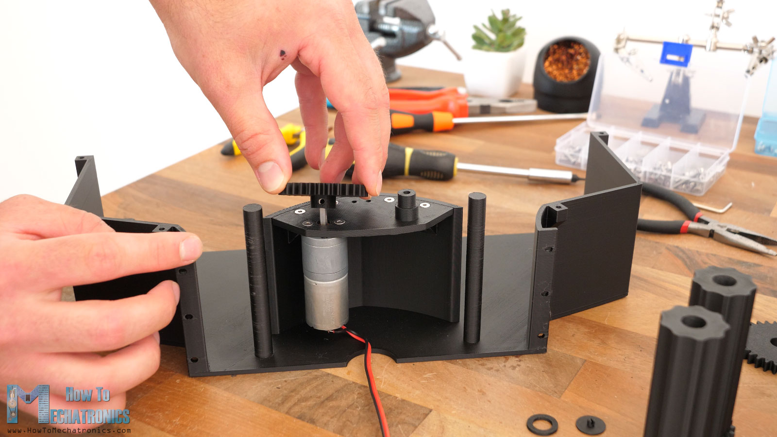
Once we have the two barrel bases in place, we can put the drive gear in the middle in between them. The gear will be driven by a 12V DC motor. In my case that’s 1300rpm motor but it can be as low as 300rpm.
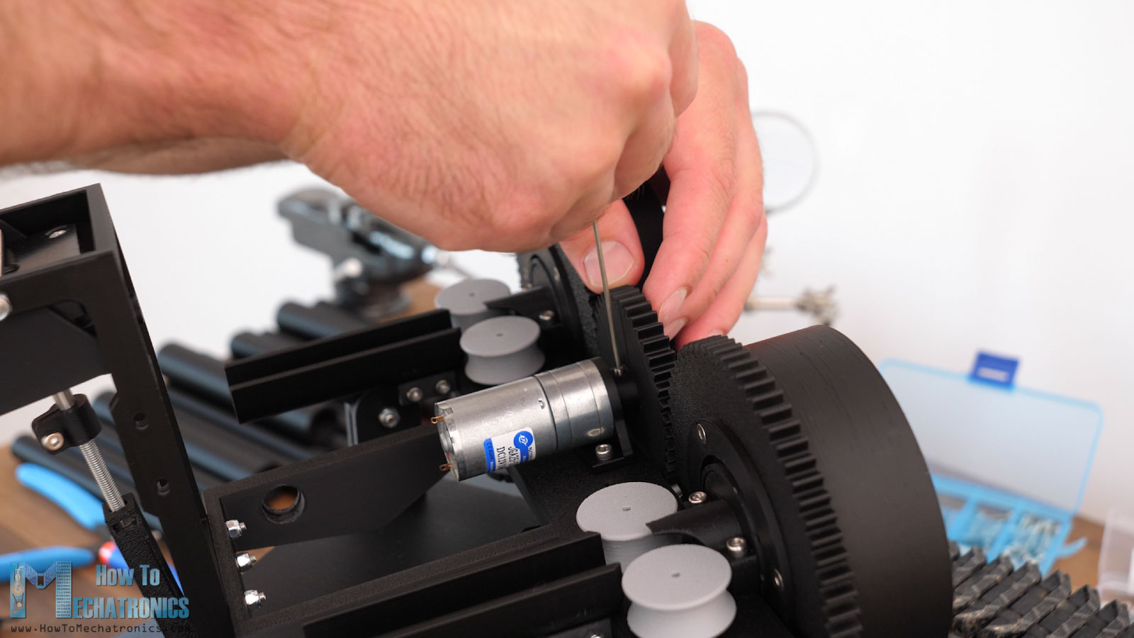
The DC motor is fixed in place with the help of a bracket that is attached to the tilt platform. Using a grub screw, we can secure the gear to the motor shaft.
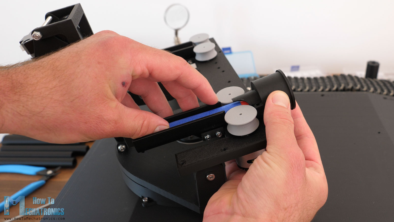
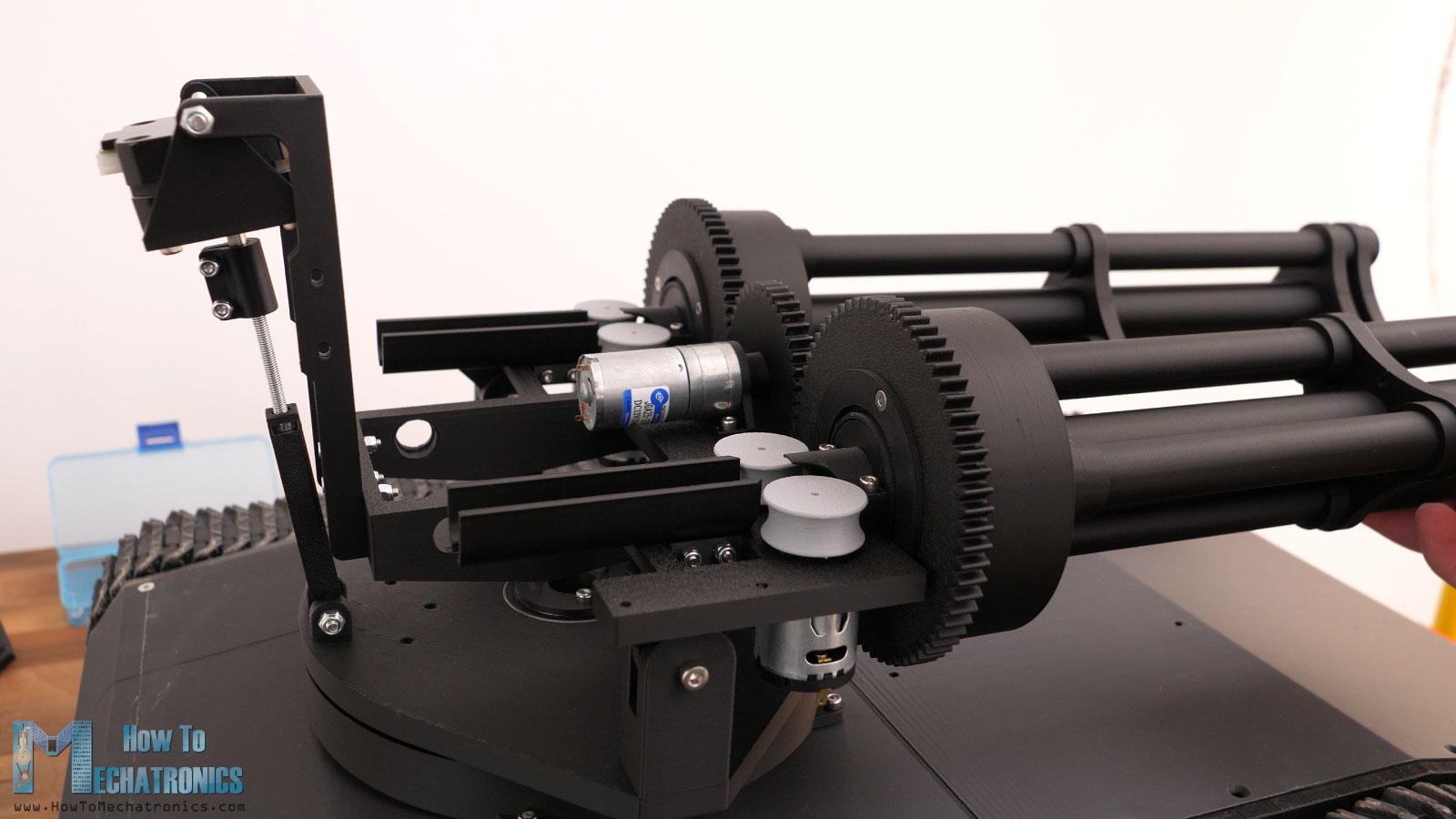
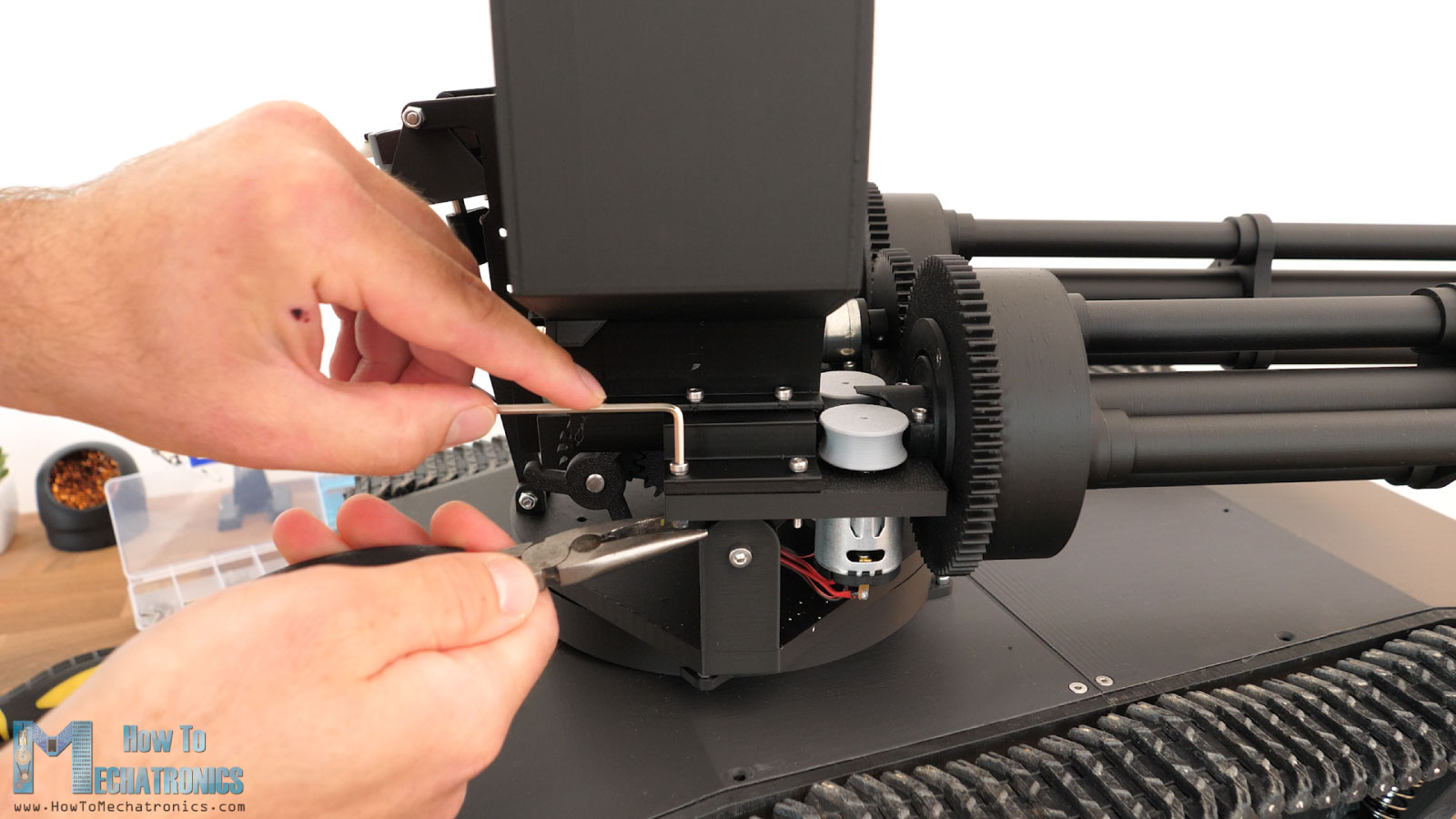
Now let’s make this turret looks super cool. We will assemble the barrels and make it look like a minigun. I chose to have one bigger barrel in the middle, through which the nerf dart will pass through, and three more smaller barrels around that one for getting that cool visual appearance. For easier 3D printing, I divided the barrels in half. They are not exactly in half, but with a slight difference in length, so we should keep that in mind. For assembling them, we will use these brackets which are both functional and add up to that cool looking factor.
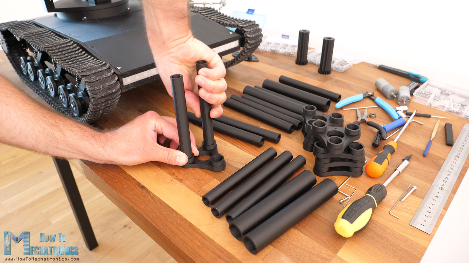
So, we simply insert the barrels into the brackets but here it is important to have a proper fit between them, so they stay firmly in place. To achieve that, we can play with the already mentioned, horizontal expansion settings in your slicer when 3D printing. You should do some tests prints first I guess in order to find out what values will give you this interference fit.
In the first section, the central barrel should be the longer one, while the three other barrels should be the shorter ones. The second bracket should be inserted in the opposite direction, half-way through the outside barrels.
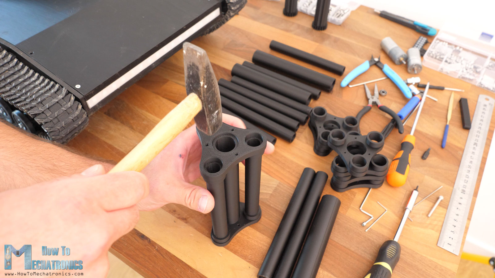
Then we can add the second set of barrels, and the brackets at the end. Here I’m inserting two brackets at the end, again just for better visual appearance. The outside barrels should be flash with the last bracket, and the central bracket pulled back a little bit.
Lastly, we can simply attach this barrel’s sub-assembly to the barrel base with three M3 bolts.
We need to repeat the same process for the other side, and we are done with the barrels.
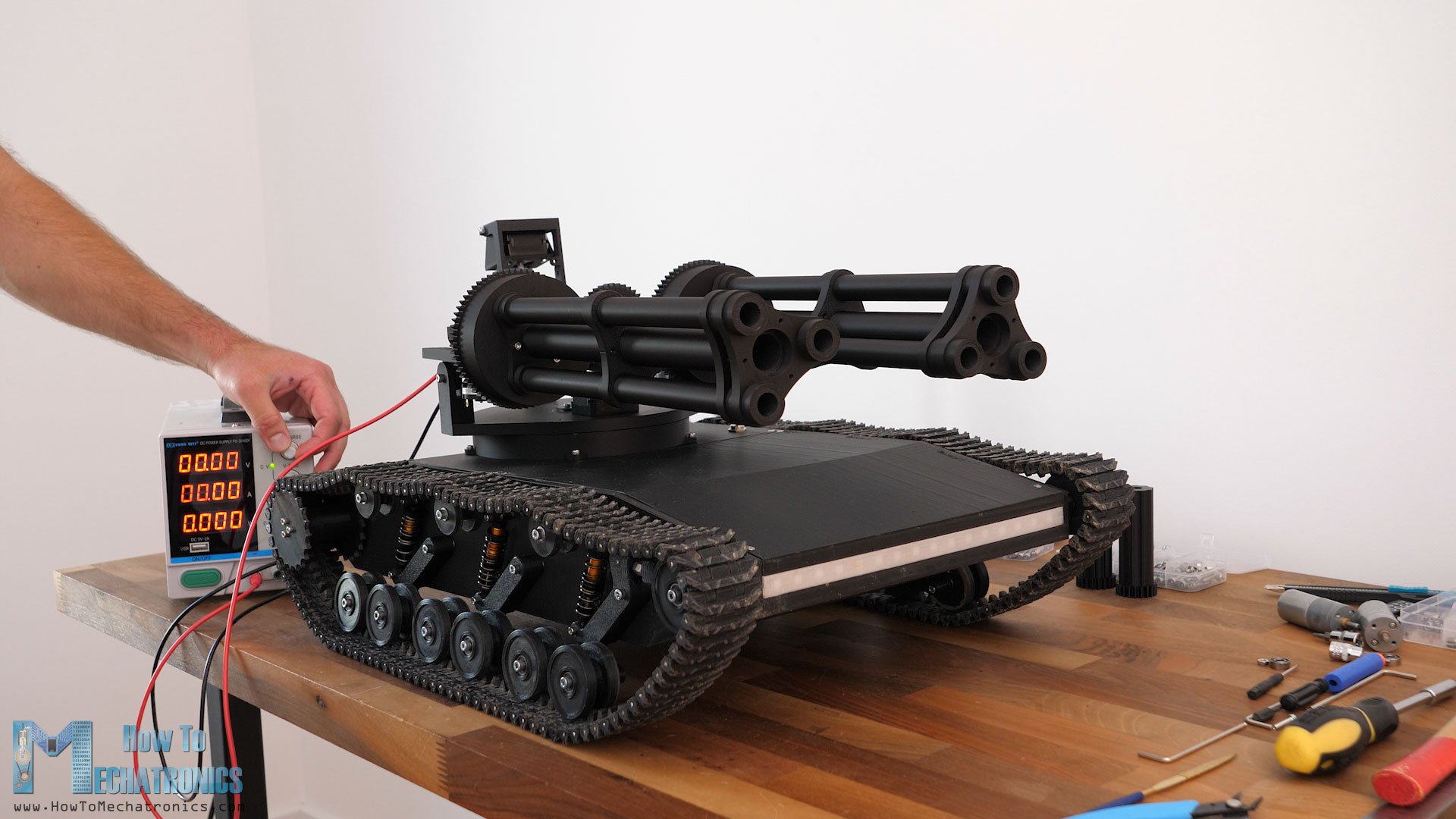
They just look super cool. Even cooler when I powered their motor.
However, we can notice that the weight of the two barrels significantly bends the tilt platform. When doing this test, the platform even broke. It was actually really bad designed.
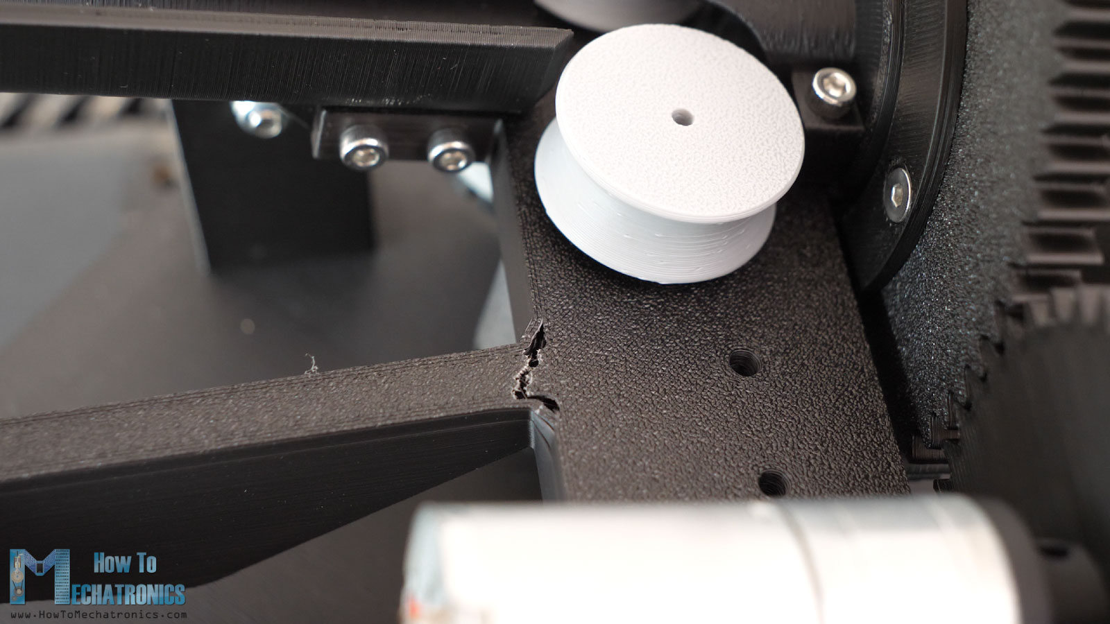
A single point of around 8mm was supporting the entire weight in relationship with the tilt joints on the sides. So, of course, I had to redesign it to make it sturdier. Luckily, there was a room to add more material and increasing the strength at that point of the part.
I also connected the sides with the central part for some additional strength. These are just small connections with 6x7mm dimension, because that was the only available space for that purpose, but still mean a lot for improving the sturdiness of the entire platform.
I also increased the number of walls and the infill density when 3D printing the redesigned part. It feels so much sturdier now. I reassembled everything and tested it again. It was much better, though now the coupler between the stepper motor and the threaded rod failed. Though, that wasn’t a big deal, as I just made the coupler longer in order to tighten it with two bolts instead of one.
The tilt mechanism still wobbles after all the added weight, but it doesn’t come just from the tilt mechanism, but also from the pan joint, which seemed a little bit lose. That’s why I said that I will upgrade the pan base part to have 6 supporting bearings instead of 4.
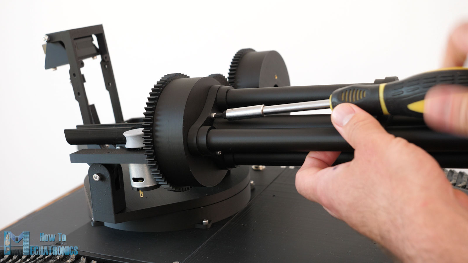
Anyhow, we can move on with assembling the nerf darts pusher mechanism. First, we can insert the DC motor in place. Here I’m inserting a 1300rpm one, but then I will realize that that’s why too high speed for that purpose. We need maximum 100rpm motor here. Anyway, this DC motor, through a gearset, will drive a 6mm shaft to which we will attach the pusher parts on both sides.
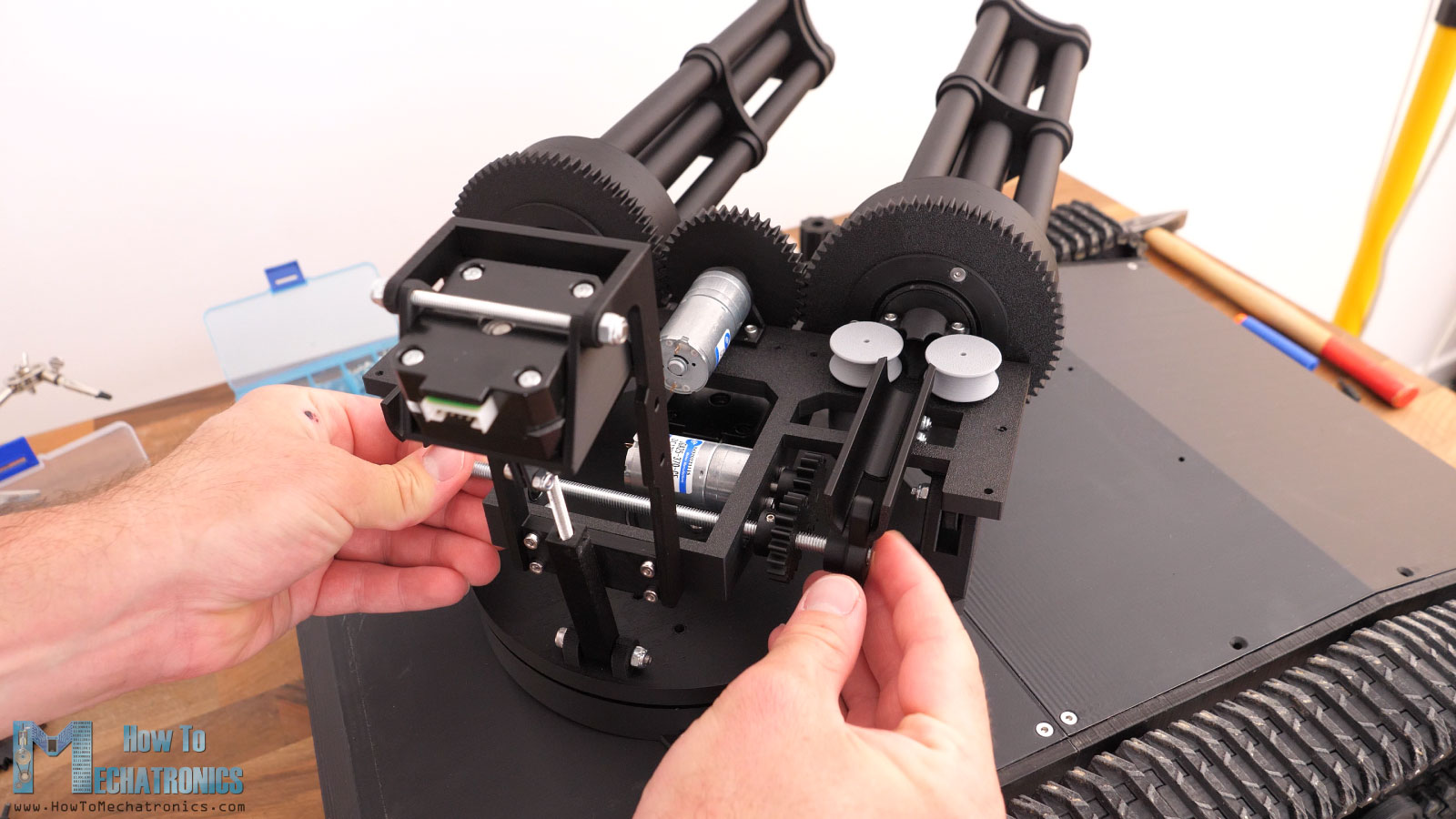
As a shaft I’m using an M6 threaded rod, because it’s much cheaper and easier to get. Threaded rods are not that accurate compared to a proper 6mm shaft, especially when used in combination bearings, but that’s fine as we don’t need that much accuracy for this mechanism.
The length of this shaft is 166mm, and it’s secured in place with the help of some M6 nuts in the inner section of the tilt platform and press against the ball bearings.
The gear and the pushers are secured to the shaft with some grub screws. The pusher mechanism seems to work properly for now.
All right, so next we can install the magazine for the nerf darts. But before we do, it’s better to add the wires to the DC motors, as currently we have more access to them. We need like 30cm wires for each motor.
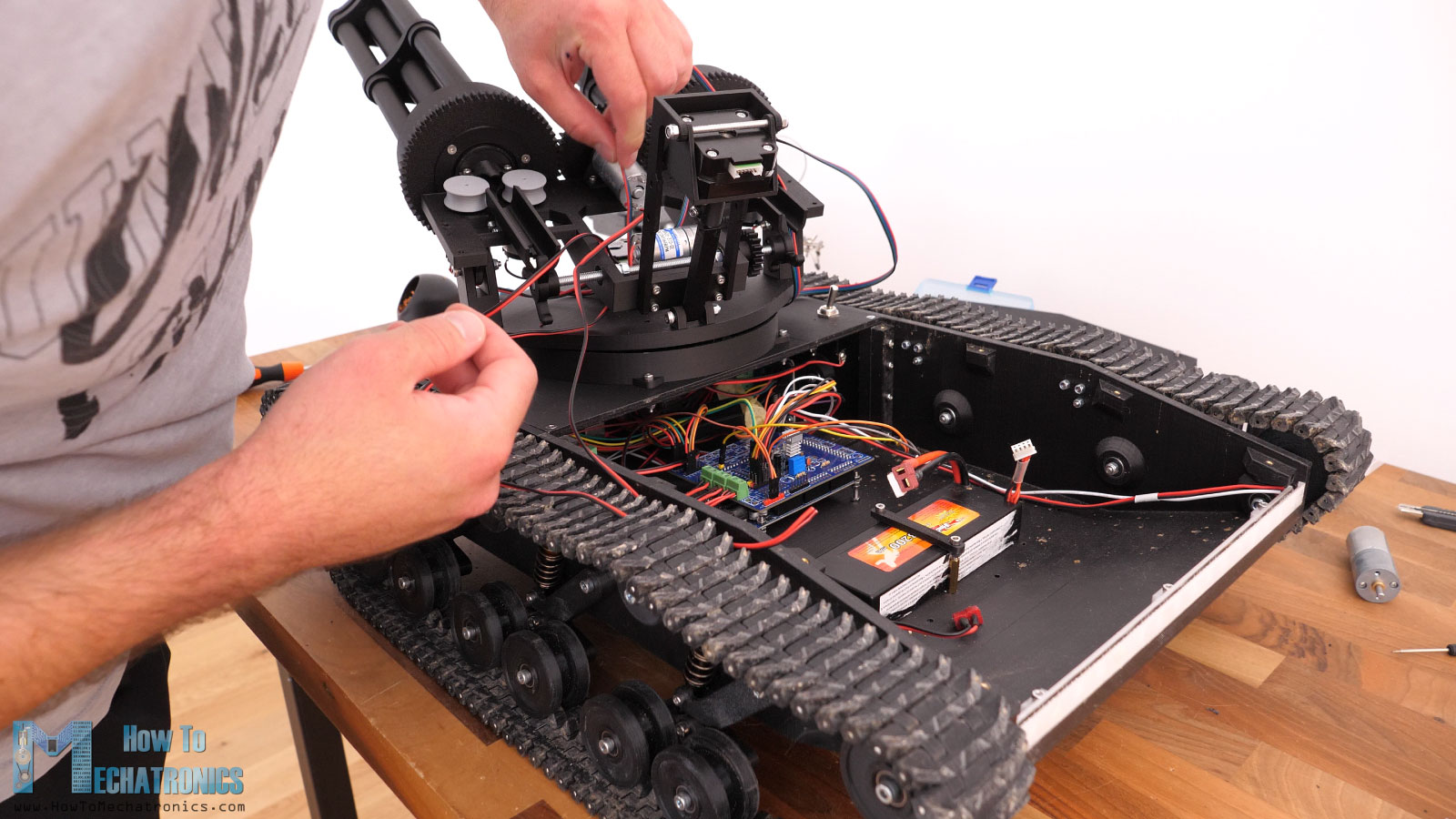
As for the flywheel’s motors, I connected them all together in parallel, so only single + and – wire would to the controller, as all of them should work at the same speed and be controlled at the same time.
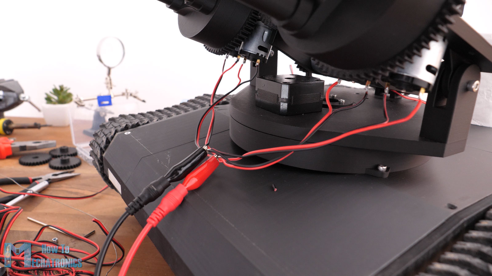
Though, we should test the polarity, and make sure that each flywheel spin in the right direction for firing the nerf darts. We can also connect the stepper motor and then pass all wires through the central opening.
Now we can move on with installing the darts magazine. This one can hold around 200 darts, but we can easily increase the capacity by simply expanding it up or to the sides. For connecting to the tilt platform, we will these brackets and some M3 bolts. But before we do that, we should install the DC motor for the magazine rollers.
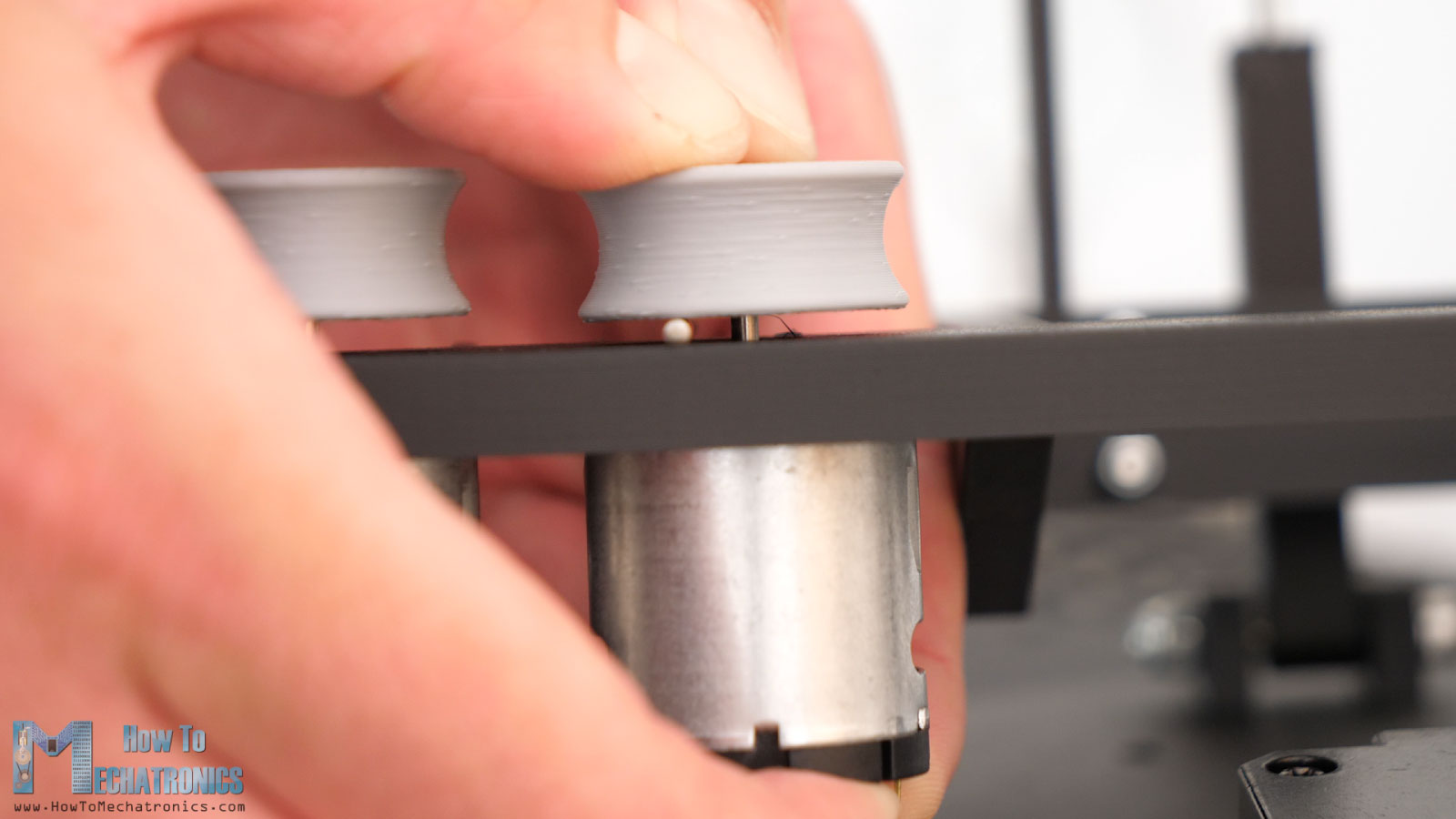
That one goes on a bracket that we first need to secure it to the magazine with some M3 bolts. The DC motor I’m installing here is 12V 50rmp, but we could go even lower like 20rpm. As the rollers will operate at a very low rpm, the shafts for them are just 3D printed.
This motor will drive the rollers through a set of gears. You see here the left roller is directly driven by the motors gear, and the right roller is driven by another gear in between the roller and the motor gear in order to produce opposite direction.
We need to install some threaded inserts to the magazine, and then we can use them for attaching the cover for it at the back side.
Now we can insert the magazine in place and secure it to the tilt platform with the brackets and some M3 bolts and nuts.
And that’s it, out nerf minigun turret is completed, except for some covers that I will later add for enclosing and protecting the moving parts.
Now we can connect the DC motors to power, to see how everything works in motion. Now it’s also a good time to add same nerd darts in the magazine to check whether all of this actually work.
My initial testing of the nerf minigun system were not that well. The darts jammed often so I had to come up with several adjustments to the design to get them working.
I had to add another roller on the opposite site to have better loading to the system. That meant I had to redesign the hole magazine. I did that any here’s how it looks after those changes.
Finally, after so many tweaking and updates, the work of the nerf darts loader is acceptable.
I wouldn’t say it’s like 100% perfect because it can still get stuck from time to time, but still, I think it’s good enough.
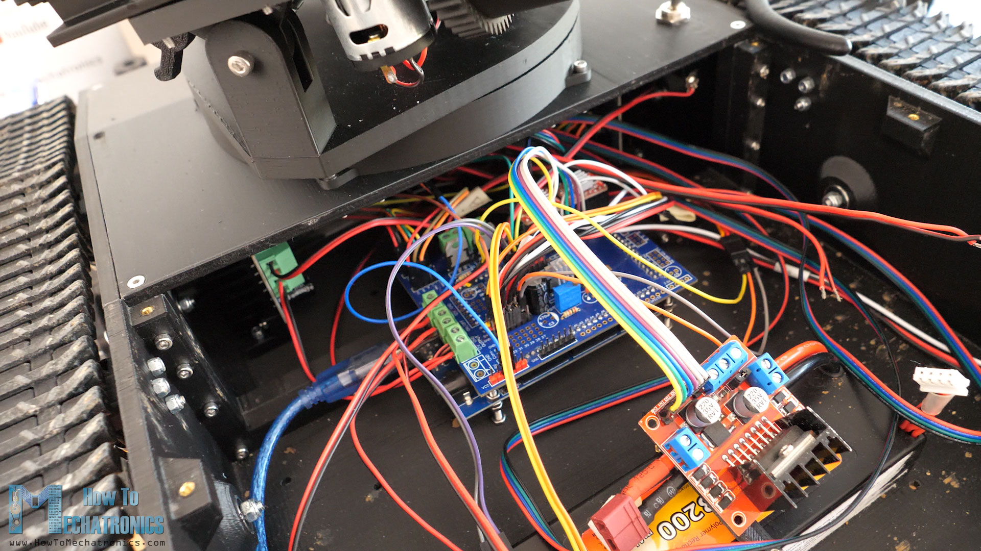
Anyhow, we can move on now with the electronics or connect the turret to the custom-made PCB that I have on the tank.
Circuit Diagram
Let’s take a look at the electronics for the NERF Minigun Turret and the RC tank and explain how it works. The brain is an ATmega2560 microcontroller-based board or an Arduino MEGA board.
Bill of Materials
You can get the components from the links below:
| Component | Quantity | Purchase Links |
|---|---|---|
| 12000RPM 12V DC Motor RS360 | 4 | Amazon | AliExpress | Temu |
| 300RPM 12V DC Motor – JGA25-370 | 1 | Amazon | AliExpress | Temu |
| 60RPM 12V DC Motor – JGA25-370 | 1 | Amazon | AliExpress | Temu |
| 30RPM 12V DC Motor – JGA25-370 | 1 | Amazon | AliExpress | Temu |
| L298N DC Motor Driver | 1 | Amazon | AliExpress | Temu |
| NEMA17 30mm Stepper Motor | 2 | Amazon | AliExpress | Temu |
| A4988 Stepper Driver | 2 | Amazon | AliExpress | Temu |
| MOSFET TIP122 | 2 | Amazon | AliExpress | Temu |
| DIODE 1N4007 | 2 | Amazon | AliExpress | Temu |
| Terminal Block Connector | 2 | Amazon | AliExpress | Temu |
| Wires ~20AWG | ~3m | Amazon | AliExpress | Temu |
| Resistors – 1k x2 | Amazon | AliExpress | Temu | |
| Capacitors – ~63uF x2 | Amazon | AliExpress | Temu |
Disclosure: These are affiliate links. As an Amazon Associate I earn from qualifying purchases.
As for the BOM for the RC tank, please check the RC Tank article.
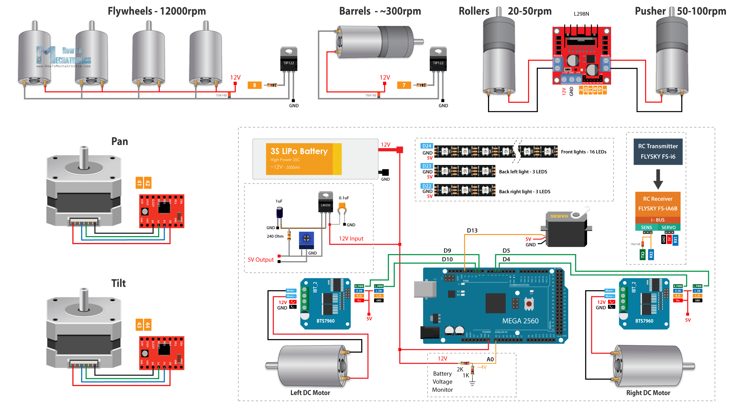
So, the four DC motors for the flywheels will be controlled through a single MOSFET with a PWM signal. And another MOSFET for the barrels motor. We don’t need to change the direction of ration of these two motors, so that’s why we are fine with just controlling their speed with PWM signals. On the other hand, for the rollers, and the pusher motors, we will use a dedicated DC motor drives which also have H-bridges, so that we are able to change the direction of rotation. I want to be able to change the rotation direction because in case of getting the darts stuck, we can activate the rollers and the pusher to go in reverse direction and so unstuck the darts. This function turned out that it works.
For driving the two NEMA17 stepper motors the pan and tilt mechanism we are using two A4988 stepper drivers.
Custom PCB
I pulled out the custom-build PCB from the Arduino mega board and soldered in place these few additional parts.
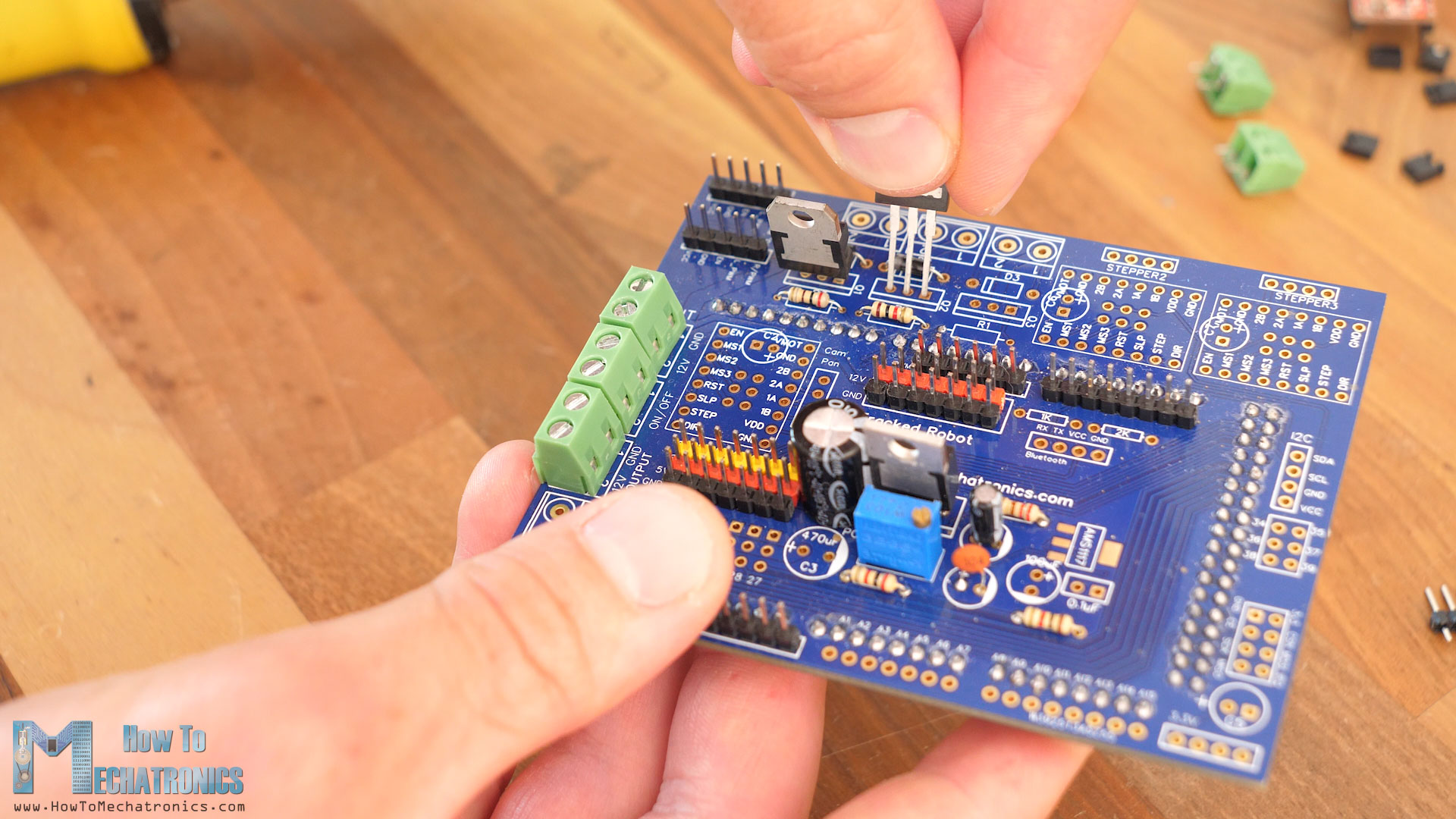
You see, when I designed this PCB in my previous video I planned ahead and included dedicated spots for connecting the MOSFETS and well as the A4988 stepper motor drivers.
You can find and download the Gerber file for this PCB, from PCBWay projects sharing community through which you can also directly order the PCB.
Yes, I ordered the PCB from PCBWay. PCBWay provides great PCB manufacturing and assembly services which I highly recommend.
Anyway, we should connect everything as described in the circuit diagram and put back the PCB in place to the Arduino Mega board.
Though, instead of using the more efficient DRV8871 DC motor drivers for driving the rollers and the pusher motors, I ended up using the outdated and inefficient L298N DC motor driver. I simply couldn’t get the motors work with the first drivers; I couldn’t control their speed properly with the PWM signal. I guess the motor type simply didn’t match with the DRV8871 drivers. With the L298N driver, the PWM control for them worked properly.
For powering the tank, previously I used 3S Lipo battery, which was ok, but now I think that a 4S Lipo battery is more appropriate.
With the 3S battery, when the cells voltage drops to their nominal value, 3.7V, the total output is 11.1V, which is already below 12V and so we lose power to the motors. With the 4S batter, the nominal total out is 14.8, which is actually way above 12V, but we can use a buck converter to fix the output 12V.
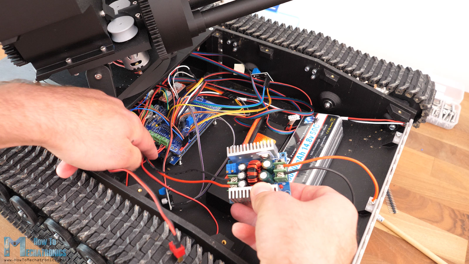
That way we will always get that fixed 12V at all times no matter if the battery is fully charged to 16.8V or drained to 14 volts. Though, we should make sure we first set the desired voltage before connecting it to the circuit.
What’s left to do now is to program the Arduino Mega board and give live to the turret as well. I will just quickly go through the Arduino code and on the website article you will find more details how it works.
Programing the NERF Minigun Turret and RC Tank
You can find and download the code together with the 3D files on Cults3D.
So, using the IBusBM library we read the incoming data from the RC Transmitter.
// Reading the data comming from the RC Transmitter
  IBus.loop();
  ch0 = IBus.readChannel(0);  // ch0 - left and right;
  ch1 = IBus.readChannel(1);  // ch1 - forward and backward;
  ch2 = IBus.readChannel(2);  // ch2 - tilt;
  ch3 = IBus.readChannel(3);  // ch3 - pan;
  ch4 = IBus.readChannel(4);  // ch4 - firing power;
  ch5 = IBus.readChannel(5);  // ch5 - firing rate;
  ch6 = IBus.readChannel(6);  // ch6 - Gear shifter
  ch7 = IBus.readChannel(7);  // ch7 - unstuck - reverse rotation
  ch8 = IBus.readChannel(8);  // ch8 - lights
  ch9 = IBus.readChannel(9);  // ch9 - fireCode language: JavaScript (javascript)
We are using all 10 channels of the popular Flysky fs-i6 RC transmitter. This is officially a 6 channel RC transmitter, but we can turn of 4 more channels to work.
We convert the incoming data into suitable values depending on what we are using them for.
// Stepper Pan
  if (ch3 >= 1000 && ch3 < 1485) {
    panVal = map(ch3, 1000, 1485, -400, 0);
  } else if (ch3 > 1515 && ch3 <= 2000) {
    panVal = map(ch3, 1515, 2000, 0, 400);
  } else {
    panVal = 0;
  }
  stepperPan.setSpeed(panVal);  // Pan
  stepperPan.run();Code language: HTML, XML (xml)
For example, we convert the left joystick channel 3 incoming data, into values from 0 to 400, which are then used with the setSpeed fuction within the AccellStepper library, to run the stepper motor with an appropriate speed.
On the other hand, for controlling the DC motors, we convert the incoming data into values from 0 to 255, for driving the motors with PWM values using the analogWrite() function.
  if (ch9 == 2000) {
    firingPower = map(ch4, 1000, 2000, 0, 255);

    analogWrite(M4_Flywheels, firingPower);

    firingRate = map(ch5, 1000, 2000, 0, 255);

    barrelsSpeed = firingRate;
    if (barrelsSpeed > 120) {
      barrelsSpeed = 120;
    };

    analogWrite(M3_Barrels, barrelsSpeed);

    digitalWrite(M6_MagRoller_IN1, LOW);
    digitalWrite(M6_MagRoller_IN2, HIGH);
    analogWrite(M6_MagRoller_enB, firingRate);

    digitalWrite(M5_Feeder_IN1, LOW);
    digitalWrite(M5_Feeder_IN2, HIGH);
    analogWrite(M5_Feeder_enA, firingRate);
  }
For better understanding of the code, check the code itself, as it contains comments and descriptions how particular lines work.
Testing the NERF Minigun Turret
Once we upload the code, we can power up the robot platform and the RC Transmitter for testing it out. On the transmitter display we can notice the LiPo battery voltage, as well as the receiver and the transmitter voltage. With the right joystick we control the tank movement. I set the lights control to the left 3-way rocker switch so that we can choose from two different light modes.
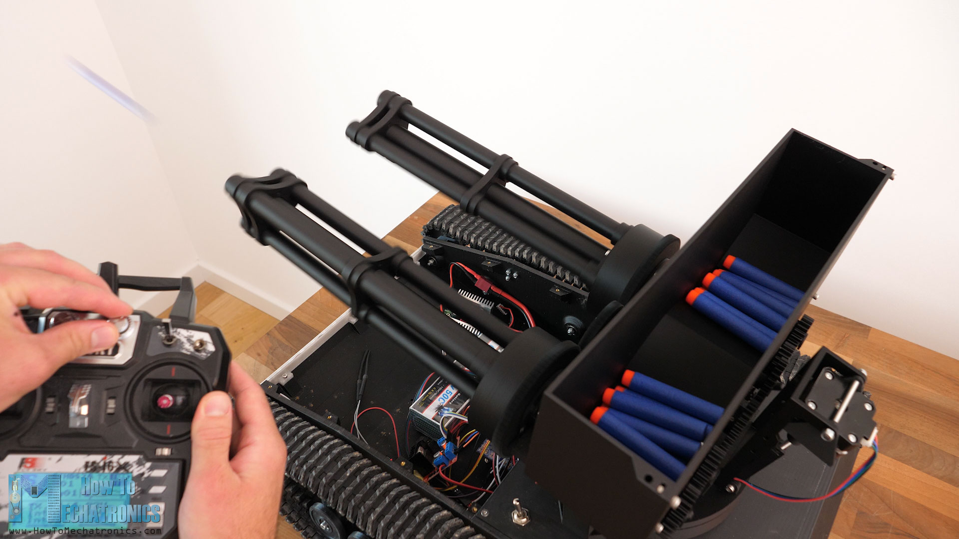
With the left joystick, we control the pan and tilt system of the turret. With the very right joystick we activate the nerf darts firing. With the right potentiometer we can control the firing rate, and with the left potentiometer the firing power, i.e. the flywheels rpm. The cool part is that everything can work simultaneously. The tank can fire nerf darts while driving and panning and tilting and having the lights turned on.
Nevertheless, that was a hell of a ride to be honest. I faced so many problems when designing and building this project, and that’s why I decided to show you all of that, so that you can see what it takes sometimes to make a project like this.
I hope you enjoyed this tutorial and learned something new.
Hi,
I really want to build this one. But before I buy all files, I want to make sure PCB uploaded to PCB way is correct. There are multiple messages saying there is an issue with a trace. Can you confirm it’s been fixed?
Thank you! Awesome project, looking forward to build it
Hey, I’ve just check the PCB and updated. There were two traces crossing and also some minor adjustments to the traces distance from the pads in order to doesn’t show warnings.
I hope you will have fun building it.
Cheers!
Good work!
You said: “I mean, these new holes will be updated to the original tank 3D model files, so if you are building the tank now the holes will be there.”
Have the files on Cults3D already been updated? I just find the old ones.
Hey, thanks!
I’ve just updated the files, so now the holes are there. 🙂
Cheers