In this tutorial we will learn how to control high voltage devices using Arduino and a relay module. You can watch the following video or read the written tutorial below.
Overview
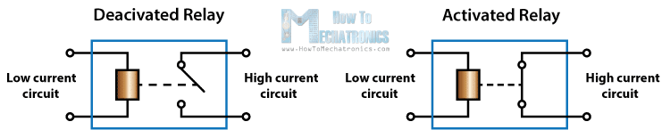
We can control high voltage electronic devices using relays. A Relay is actually a switch which is electrically operated by an electromagnet. The electromagnet is activated with a low voltage, for example 5 volts from a microcontroller and it pulls a contact to make or break a high voltage circuit.
HL-52S Relay Module
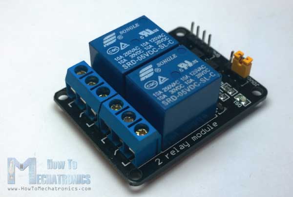
As an example for this Arduino Relay Tutorial we will use the HL-52S 2 channel relay module, which has 2 relays with rating of 10A @ 250 and 125 V AC and 10A @ 30 and 28 V DC. The high voltage output connector has 3 pins, the middle one is the common pin and as we can see from the markings one of the two other pins is for normally open connection and the other one for normally closed connection.
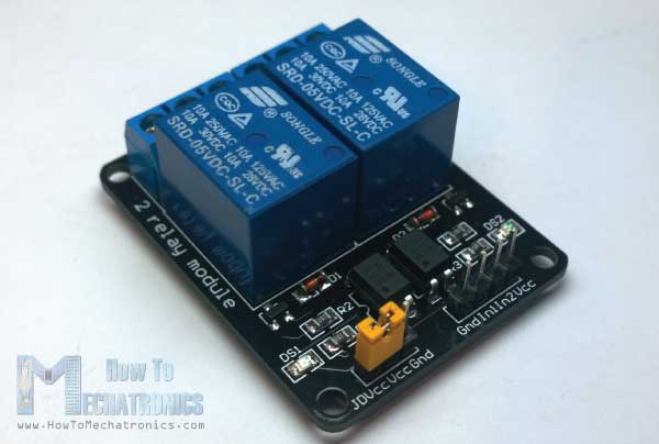
On the other side of the module we have these 2 sets of pins. The first one has 4 pins, a Ground and a VCC pin for powering the module and 2 input pins In1 and In2. The second set of pins has 3 pins with a jumper between the JDVcc and the Vcc pin. With a configuration like this the electromagnet of the relay is directly powered from the Arduino Board and if something goes wrong with the relay the microcontroller could get damaged.
Components needed for this Arduino Relay tutorial
You can get the components from any of the sites below:
- 5V Relay Module………………………… Amazon / Banggood / AliExpress
- Arduino Board …………………………… Amazon / Banggood / AliExpress
- Breadboard and Jump Wires ……… Amazon / Banggood / AliExpress
- Cable, Plug, Socket
Disclosure: These are affiliate links. As an Amazon Associate I earn from qualifying purchases.
Circuit Diagram
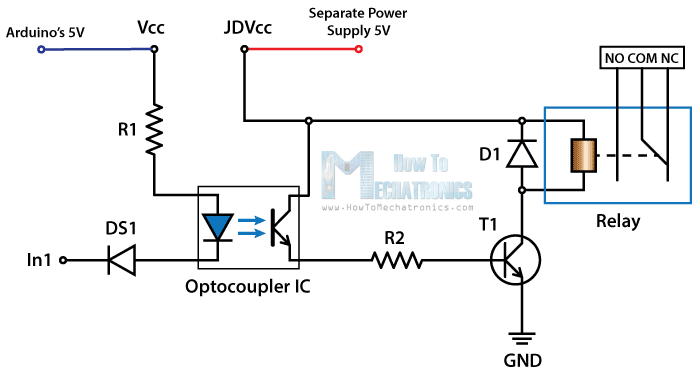
For better understanding let’s see the circuit schematics of the relay module in this configuration. So we can see that the 5 volts from our microcontroller connected to the Vcc pin for activating the relay through the Optocoupler IC are also connected to the JDVcc pin which powers the electromagnet of the relay. So in this case we got no isolation between the relay and the microcontroller.
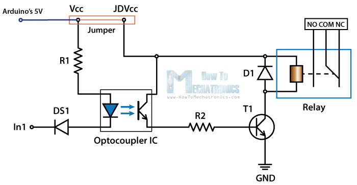
In order to isolate the microcontroller from the relay, we need to remove the jumper and connect separate power supply for the electromagnet to the JDVcc and the Ground pin. Now with this configuration the microcontroller doesn’t have any physical connection with the relay, it just uses the LED light of the Optocoupler IC to activate the relay.
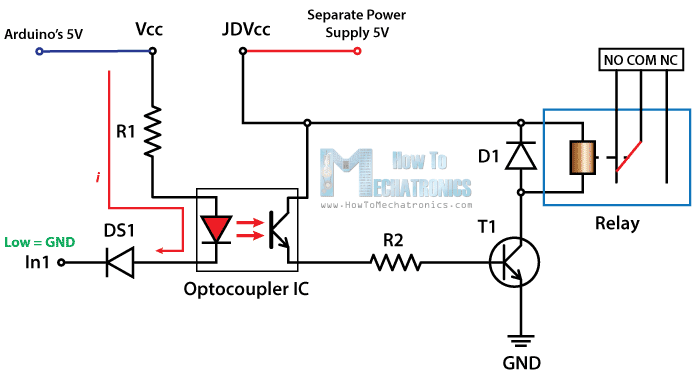
There is one more thing to be noticed from this circuit schematics. The input pins of the module work inversely. As we can see the relay will be activated when the input pin will be LOW because in that way the current will be able to flow from the VCC to the input pin which is low or ground, and the LED will light up and active the relay. When the input pin will be HIGH there will be no current flow, so the LED will not light up and the relay will not be activated.
High Voltage Warning
Before we continue with this tutorial, I will warn you here that we will use High Voltage which if incorrectly or improperly used could result in serious injuries or death. So be very caution of what you are doing because I take no responsibility for any of your actions.

How to use the Arduino Relay Module with the High Voltage devices
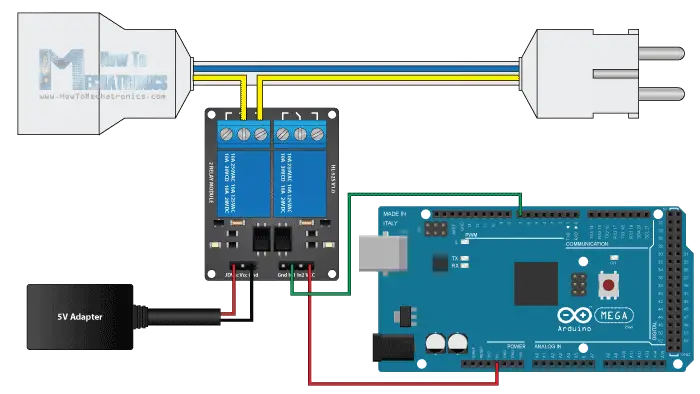
First let’s take a look at the circuit diagram. As previously described we will use a 5V Adapter as a separate power supply for the electromagnet connected to the JDVcc and the Ground pin. The Arduino’s 5V pin will be connected to the Vcc pin of the module and the pin number 7 to the In1 input pin for controlling the relay. Now for the HIGH Voltage part we need a power plug, a socket and a cable with two wires. One of the two wires will be cut and connected to the common and the normally open pin of the module output connector. So with this configuration when we will activate the relay we will get the high voltage circuit closed and working.
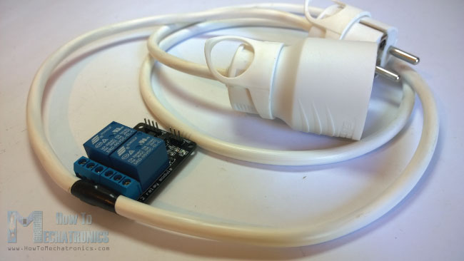
Here’s how made the cable. So I bought a plug, a socket and a cable. Then I carefully cut the cable and cut one of the wires as shown in the picture below and connect them to the normally open connection pins of the relay module. Also connected the ends of the cable to the plug and the socket.
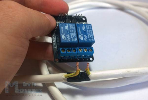
*Note: Make sure you use the other wires, not the “Yellow & Green” wire as it is meant to be used for Ground.
Here’s the final appearance of my cable ready for use. However before you use your cable make sure it’s working properly. You can check it using a multimeter or test it with a low voltage first.
Arduino Relay Tutorial Source Code
Now what’s left for this tutorial is to make a simple code and test relay module how it will work. Here’s the simple code, we will just use the pin number 7 for controlling the relay, so we will define it as output and make a program that will just activate and deactivate the relay each 3 seconds. I will mention once again here that the input of the module works inversely so a logic low at the input will actually active the relay and vice versa.
int in1 = 7;

void setup() {
  pinMode(in1, OUTPUT);
  digitalWrite(in1, HIGH);
}

void loop() {
  digitalWrite(in1, LOW);
  delay(3000);
  digitalWrite(in1, HIGH);
  delay(3000);
}Code language: Arduino (arduino)
There is a demonstration of this example at the end of the video of this tutorial. I tested 3 devices on it. First a 100W light bulb, then a desk lamp and a fan heater. All of these devices work on 220V.
So that’s how we can control any High Voltage Device using Arduino or actually any other microcontroller. And of course the possibilities are now endless, for example we can control the devices using TV Remote, Bluetooth, SMS, Internet, and so on.