In this Arduino Bluetooth Tutorial we will learn how use the HC-05 module for controlling Arduino via Bluetooth communication. You can watch the following video or read the written tutorial below for more details.
Overview
For this tutorial I made two example, controlling the Arduino using a smartphone and controlling the Arduino using a laptop or a PC. In order not to overload this tutorial, in my next tutorial we will learn how we can configure the HC-05 Bluetooth module and make a Bluetooth communication between two separate Arduino Boards as master and slave devices.
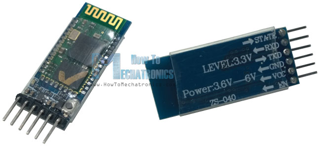
Before we start with the first example, controlling an Arduino using a smartphone, let’s take a closer look at the HC-05 Bluetooth module. Comparing it to the HC-06 module, which can only be set as a Slave, the HC-05 can be set as Master as well which enables making a communication between two separate Arduino Boards. There are several different versions of this this module but I recommend the one that comes on a breakout board because in that way it’s much easier to be connected. The HC-05 module is a Bluetooth SPP (Serial Port Protocol) module, which means it communicates with the Arduino via the Serial Communication.
You can get the components needed for this Arduino tutorial from any of the sites below:
- HC-05 Bluetooth Module ……………. Amazon / Banggood / AliExpress
- Arduino Board …………………………… Amazon / Banggood / AliExpress
- Breadboard and Jump Wires ……… Amazon / Banggood / AliExpress
Disclosure: These are affiliate links. As an Amazon Associate I earn from qualifying purchases.
Circuit Schematics
Here’s how we need to connect the module to the Arduino Board.
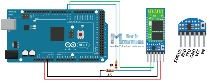
The particular module that I have can be powered from 3.6 to 6 volts, because it comes on breakout board which contains a voltage regulator. However, the logic voltage level of the data pins is 3.3V. So, the line between the Arduino TX (Transmit Pin, which has 5V output) and the Bluetooth module RX (Receive Pin, which supports only 3.3V) needs to be connected through a voltage divider in order not to burn the module. On the other hand, the line between the Bluetooth module TX pin and the Arduino RX pin can be connected directly because the 3.3V signal from the Bluetooth module is enough to be accepted as a high logic at the Arduino Board.
Arduino Bluetooth Communication Example Source Code
So, now we are ready to make the Arduino code for enabling the communication between the Arduino board and the smartphone. We will make a simple example, just turning on and off a LED but it will be good enough for understanding the communication.
#define ledPin 7
int state = 0;

void setup() {
  pinMode(ledPin, OUTPUT);
  digitalWrite(ledPin, LOW);
  Serial.begin(38400); // Default communication rate of the Bluetooth module
}

void loop() {
  if(Serial.available() > 0){ // Checks whether data is comming from the serial port
    state = Serial.read(); // Reads the data from the serial port
 }

 if (state == '0') {
  digitalWrite(ledPin, LOW); // Turn LED OFF
  Serial.println("LED: OFF"); // Send back, to the phone, the String "LED: ON"
  state = 0;
 }
 else if (state == '1') {
  digitalWrite(ledPin, HIGH);
  Serial.println("LED: ON");;
  state = 0;
 }
}Code language: PHP (php)
Description: First we need to define the pin to which our LED will be connected and a variable in which we will store the data coming from the smartphone. In the setup section we need to define the LED pin as output and set it low right away. As mention previously, we will use the serial communication so we need to begin the serial communication at 38400 baud rate, which is the default baud rate of the Bluetooth module. In the loop section with the Serial.available() function we will check whether there is available data in the serial port to be read. This means that when we will send data to the Bluetooth module this statement will be true so then using the Serial.read() function we will read that data and put it into the “state” variable. So if the Arduino receive the character ‘0’ it will turn the LED off and using the Serial.println() function it will send back to the smartphone, via the serial port, the String “LED: OFF”. Additionally we will reset the “state” variable to 0 so that the two above lines will be executed only once. Note here that the “state” variable is integer, so when we receive the character ‘0’ that comes from smartphone, the actual value of the integer “state” variable is 48, which corresponds to character ‘0’, according to the ASCII table.. That’s why in the “if” statement we are comparing the “state” variable to a character ‘0’. On the other hand, if the received character is ‘1’, the LED will light up and the String “LED: ON” will be sent back.
Now the code is ready to be uploaded but in order to do that we need to unplug the TX and RX lines because when uploading the Arduino uses the serial communication so the pins RX (digital pin 0) and TX (digital pin1) are busy. We can avoid this step if we use the other TX and RX pins of the Arduino Board, but in that case we will have to use the SoftwareSerial.h library for the serial communication.
Related: How To Configure and Pair Two HC-05 Bluetooth Modules as Master and Slave | AT Commands
Connecting the Smartphone to the HC-05 Bluetooth Module and the Arduino
Now we are ready to connect the smartphone to the Bluetooth module and the Arduino. What we need to do here is to activate the Bluetooth and the smartphone will find the HC-05 Bluetooth module.
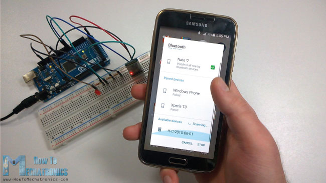
Then we need to pair the devices and the default password of the HC-05 module is 1234. After we have paired the devices we need an application for controlling the Arduino. There are many application in the Play Store for this purpose which will work with the Arduino code that we wrote. However, I made my own custom application for this tutorial using the MIT App Inventor online application. This is a great and easy to use application for building Android application and in my next tutorial you can find a detailed step by step guide how to build your own custom Android application for your Arduino Project.
You can download the app that I made for this example here:
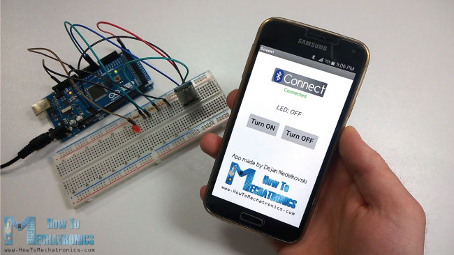
With the connect button we will connect the smartphone to the Bluetooth module and the status text below the button will tell us whether we have successfully connected. Using the “Turn ON” and “Turn OFF” buttons we can turn on and off the LED. The text above the buttons is the one that the Arduino is sending back to the smartphone when a particular button is pressed.
Controlling Arduino Using a Laptop or PC via Bluetooth Communication
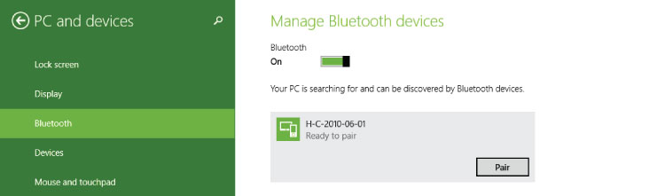
Let’s see how we can control the Arduino via Bluetooth using a Laptop or a PC. So, first we need to pair our laptop to the HC-05 Bluetooth module and we can do that from the Laptop Bluetooth Settings. The laptop will discover the HC-05 module and using the ‘1234’ password we will pair the devices.
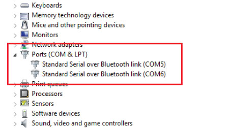
Once we will pair the devices in the Laptop Device Manager, under Ports (COM & LPT), two new entities will appear named “Standard Serial over Bluetooth link”. From here we can see the COM Port number of the serial port through which the devices will communicate.
We will stick with the same example as previously, turning on and off a LED and sending back a string to the laptop, so we will use the same Arduino code as previously described.
Processing IDE Source Code
Now using the Processing IDE we will make a program for controlling the Arduino. Here’s the source code.
import processing.serial.*;
Serial myPort;
String ledStatus="LED: OFF";

void setup(){
  size(450, 500);
  myPort = new Serial(this, "COM5", 38400); // Starts the serial communication
  myPort.bufferUntil('\n'); // Defines up to which character the data from the serial port will be read. The character '\n' or 'New Line'
}
void serialEvent (Serial myPort){ // Checks for available data in the Serial Port
  ledStatus = myPort.readStringUntil('\n'); //Reads the data sent from the Arduino (the String "LED: OFF/ON) and it puts into the "ledStatus" variable
}

void draw(){
  background(237, 240, 241);
  fill(20, 160, 133); // Green Color
  stroke(33);
  strokeWeight(1);
  rect(50, 100, 150, 50, 10);  // Turn ON Button
  rect(250, 100, 150, 50, 10); // Turn OFF Button
  fill(255);

  textSize(32);
  text("Turn ON",60, 135);
  text("Turn OFF", 255, 135);
  textSize(24);
  fill(33);
  text("Status:", 180, 200);
  textSize(30);
  textSize(16);
  text("Program made by Dejan Nedelkovski,\n     www.HowToMechatronics.com", 80, 320);

  text(ledStatus, 155, 240); // Prints the string comming from the Arduino

  // If the button "Turn ON" is pressed
  if(mousePressed && mouseX>50 && mouseX<200 && mouseY>100 && mouseY<150){
    myPort.write('1'); // Sends the character '1' and that will turn on the LED
    // Highlighs the buttons in red color when pressed
    stroke(255,0,0);
    strokeWeight(2);
    noFill();
    rect(50, 100, 150, 50, 10);
  }
  // If the button "Turn OFF" is pressed
  if(mousePressed && mouseX>250 && mouseX<400 && mouseY>100 && mouseY<150){
    myPort.write('0'); // Sends the character '0' and that will turn on the LED
    stroke(255,0,0);
    strokeWeight(2);
    noFill();
    rect(250, 100, 150, 50, 10);
  }
}Code language: JavaScript (javascript)
Description: We need to include the Serial library and create a serial object in order to enable the serial communication, as well as, define a String variable for the led status. In the setup section we need to set the window size of the program and start the serial communication. As for the COM Port Number here we need to try one of the two COM Port numbers we previously noticed in the device manager. The next line defines the buffering of the serial port and in our case that’s until there is a new line and actually there is a new line each time the Arduino sends the String “LED: OFF” or “LED ON” because of the println() function. Next, using the serialEvent() function we check whether there is available data in the serial port to be read. If so, using the readStringUntil() function we will read that data from the serial port which has been sent from the Arduino and in our case that’s the String “LED: OFF” or “LED: ON”.
In the main draw() function, which constantly repeats, we make all the graphics and functions of the program. So first we need set the background color, the fill color, the stroke size and color and using the rect() function we draw the two buttons. Using the text() function we print all the text, including the ledStatus string that’s coming from the Arduino. What’s left now is to make the buttons functional. So using the first “if” statement we confine the area of the “Turn ON” button, so when the button is pressed the character ‘1’ will be sent over the serial port to the Arduino and that will turn on the LED. The next for lines are used to highlight the button when it’s pressed. The same procedure goes for the “Turn OFF” button.
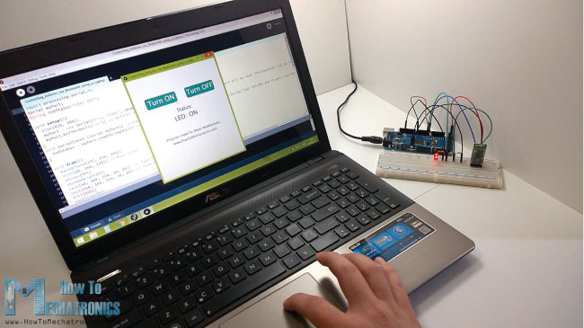
Now the program is ready, so when we will click the run button, the program will automatically activate the Bluetooth communication between the laptop and the Arduino. The HC-05 Bluetooth module will start to flash every two seconds, which indicates that the module is connect and we will be able to control the LED using our Laptop.
Thant’s all for this tutorial, but don’t forget to check my next tutorial where we will learn how we can configure the HC-05 Bluetooth module and make a Bluetooth communication between two separate Arduino Boards as master and slave devices.
Also, feel free to ask any question in the comments section below and don’t forget to check out my collection of Arduino Projects.
Hello Dejan,
Thanks for your great work & tutorials. Like your simple & detail tutorials easy to understand. I am 53 still learning your tutorials to teach school kids robotics for free in local language.
May God bless you.
Thanks again.
Gratings from Sri lanka
Thank you, I’m so glad to hear this!
Thanks for the video!
In Circuit Schematics, You’ve written the values of the resistors correctly, but their colors are reversed. 🙂
Thank you for the information.
Hello Dejan, this tutorial is quite useful, thanks a lot! I’m working on a project in which, using the MIT App Inventor, you provide a number from your smartphone and a 4 segment display shows that number. I’m relying on this tutorial and the other ones that you have laying around.
I need more help in the app inventor side of things I guess hehe.
Anyways, thanks again!
Hello,
Would this project work with arduino uno? Why did you chose the mega?
Sure, it will work with any Arduino board.
Paul Carrol, you save me 😉 . I use HC-06 and spent few hour before I find Paul reply about HC speed. Also HC-06 working only with speed 9600.
Dejan, great tutorial. Keep doing googd work 😉
Just to let others know of an issue I stumbled over: Not all HC05 modules have a default speed of 38400. Mine defaulted to 9600 so the Arduino code would not work for me until I changed that.
Also note that the Rx/Tx pins 0 & 1 on some boards (ie. Leonardo) are Serial1, so you need to change the code appropriately.
Thanks for the remarks!
Thanks for the time savings… much appreciated.
Hi ! Great tutorial! I wonder, though, i try to make an app with my students that will be able to detect the Bluetooth signal strength of 2 paired devices. Do you think that this is possible ? We want to be able from one device to check if we are getting close to the other one. (something like the game hide and seek and “cold” and “hot” when you are close to each other).
Thank you for your tutorials.
Sotiris
Thanks! I don’t think you can use these modules for such an application.
Hi, Very nice intro. I’m trying to recreate it now, but I noticed the labels for the 2 resistors in the Arduino diagram seem to be reversed from what the bands on the resistors in the diagram show. I’m not an EE, but does this matter? If it does matter, which resistor goes where? I’m guessing it doesn’t matter much(?), since I’m the first to notice it.
I just happened to notice this as I was looking for the resistors to use and was trying to match the colors on the bands in the diagram…and happened to have a resistor pack with the band descriptions on the back of it.
Thanks
Pete
Hey, that’s a great remark. Although the values of the resistors in the diagram are correct, the color labeling is wrong. So consider connecting the resistors as stated with the values. Arduino pin > 1K > 2K > GND.
I used pin 13 on my mega 2650, and 9600 for the baud rate. Also with the app I had to change from text to textcolor on the red and blue blocks for everything to show up correctly.
Very cool intro to wireless arduino control.
Hi, could you please provide the source code for the app? Not just the builded apk… I would need to expand the functionality of your simple apk for a school project
Sorry I don’t have it at this moment, but you can easily recreate it if you follow the steps in the video, you can see all blocks that I used.
Do you compile or you just send the source code to arduino Bluetooth? Which platform for you use for coding?
Arduino IDE.
Thanks for the tutorial. I had to set the baud-rate to 9600. Seems like it’s default is 9600 for HC05
This was the same for me. Changed to 9600 and all worked well.
Hi,
Thank you very much for this tutorial…i tried this and it’s working.
only one issue : when the led is on, it shows LED: OFF and vice versa.Can you help how to correct this?
It will be also helpful if the app automatically switches on Bluetooth !
Hi, I have a problem. I have connected BT module and uploaded the code but when I press buttons nothing happens.
Is it possible that I have burned the BT module?
If yes, then how can I check that?
plz my smart phone don’t detect the Bluetooth module .
Give 5V from Arduino to HC-05 bluetooth module. If You will give Less than 5V, may be, it doesn’t work.
Mr. Nedekovki, why my bluetooth HC-05 module has a 2 LEDS blinking in the same time (red & blue) ?
since I give “on” logic the led is not on.
can i request your email address ? I want to send you a photo/video about my problem
Well Done tutorials – can you please share the android code for the simple app that you have made. Thank you .
Thanks! Well the program is available for download, you probably have missed it.
Hi Dejan,
It would be extremely helpful if you could link to your source code.
Thanks in advance!
What source code? The source codes are already attached on this article.
I programmed an HC-SR04 to detect any motion that occurs in front of it. I also followed your tutorial and made an app to control the Arduino using the HC-05 bleutooth module. Every time the HC-SR04 detects motion, I want a sound to play on the phone of the person with the app installed on their phone. How do I do this?
How do I connect the LED to the Arduino for this example?
Hello,
I’m trying to make the same, but I’m getting this error “error: ‘import’ does not name a type import processing.serial.*”.
how i can fix it ???
Thanx.
What same? It sounds like you are using a Processing IDE code into Arduino IDE.
Hi,
Would you please send me a link to your YouTube video on pairing two HC-05 bluetooth modules connected to Arduinos to show how you make them master and slave? Regards, Bruce Marshall
Hi there. Well that one isn’t published yet but it will be in couple of days. 🙂