In this tutorial we will learn how to wirelessly control the Arduino robot car that we made in the previous video. I will show you three different methods of wireless control, using the HC-05 Bluetooth module, the NRF24L01 transceiver module and the HC-12 long range wireless module, as well as, using a Smartphone and a custom-made Android application. You can watch the following video or read the written tutorial below for more details.
I already have tutorials on how to connect and use each of these modules with the Arduino board, so if you need more details you can always check them. The links to each of them can be found below in the article.
Arduino Robot Car Control Using HC-05 Bluetooth Module
We will start with the Bluetooth communication, and for that purpose we need two HC-05 Bluetooth modules which need to be configured as master and slave devices.
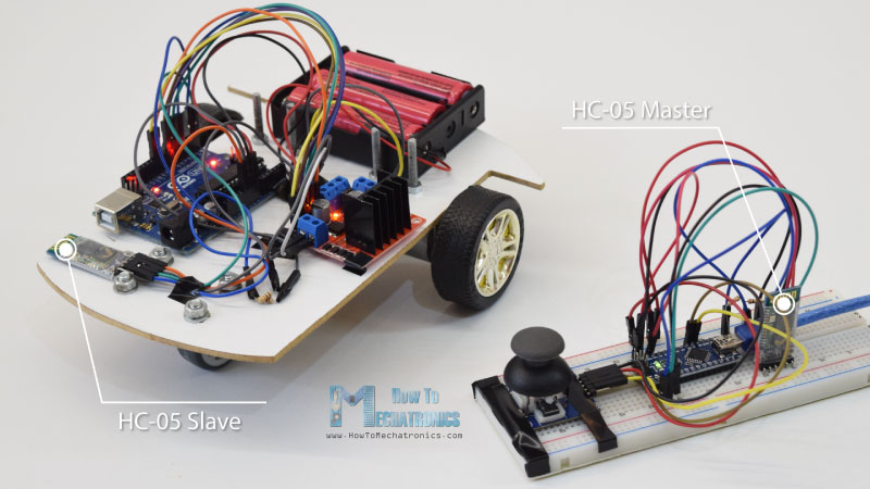
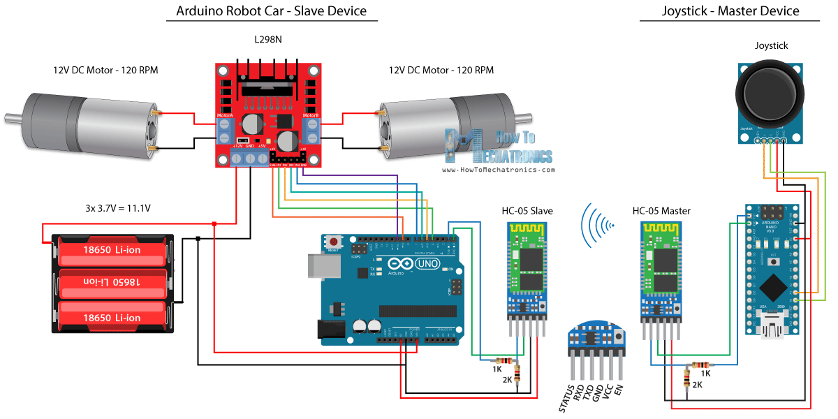
We can easily do that by using AT commands, and I set the joystick to be a master and the Arduino robot car to be a slave. Here’s the complete circuit schematic for this example:
You can get the components needed for this example from the links below:
- HC-05 Bluetooth Module ………….… Amazon / Banggood / AliExpress
- Joystick Module …………………………. Amazon / Banggood / AliExpress
- 18650 Batteries ………………………….. Amazon / Banggood / AliExpress
- 18650 Battery Charger………………… Amazon / Banggood / AliExpress
- L298N Driver …………………………….. Amazon / Banggood / AliExpress
- 12V High Torque DC Motor ………… Amazon / Banggood / AliExpress
- Arduino Board …………………………… Amazon / Banggood / AliExpress
Disclosure: These are affiliate links. As an Amazon Associate I earn from qualifying purchases.
Source Code
We will use the same code from the previous tutorial, where we control the Arduino robot car directly using the joystick, and we will make some modifications to it.
HC-05 Master code:
/*
   Arduino Robot Car Wireless Control using the HC-05 Bluetooth

                == MASTER DEVICE - Joystick ==

   by Dejan Nedelkovski, www.HowToMechatronics.com
*/

int xAxis, yAxis;

void setup() {
  Serial.begin(38400); // Default communication rate of the Bluetooth module
}

void loop() {
  xAxis = analogRead(A0); // Read Joysticks X-axis
  yAxis = analogRead(A1); // Read Joysticks Y-axis

  // Send the values via the serial port to the slave HC-05 Bluetooth device
  Serial.write(xAxis/4); // Dividing by 4 for converting from 0 - 1023 to 0 - 256, (1 byte) range
  Serial.write(yAxis/4);
  delay(20);
}Code language: JavaScript (javascript)
The code at the master device, or the joystick is quite simple. We just need to read the X and Y values of the joystick, which actually regulate the speed of the motors, and send them via the serial port to the slave HC-05 Bluetooth device. We can note here that the analog values of joystick from 0 to 1023 are converted into a values from 0 to 255 by diving them by 4.
We do this because that range, from 0 to 255, can be sent, over the Bluetooth device, as 1 byte which is easier to be accepted on the other side, or at the Arduino robot car.
So here, if the serial has received the 2 bytes, the X and Y values, using the Serial.read() function we will read both of them.
// Code from the Arduino Robot Car

// Read the incoming data from the Joystick, or the master Bluetooth device
  while (Serial.available() >= 2) {
    x = Serial.read();
    delay(10);
    y = Serial.read();
  }Code language: JavaScript (javascript)
Now we just have to convert the values back to the range from 0 to 1023, suitable for the motor control code below, which we already explained how it works in the previous video.
// Code from the Arduino Robot Car

// Convert back the 0 - 255 range to 0 - 1023, suitable for motor control code below
xAxis = x*4;
yAxis = y*4;Code language: JavaScript (javascript)
Just a quick note that when uploading the code, we need to disconnect the RX and TX pins of the Arduino board.
Complete HC-05 Slave code:
/*
   Arduino Robot Car Wireless Control using the HC-05 Bluetooth

             == SLAVE DEVICE - Arduino robot car ==

   by Dejan Nedelkovski, www.HowToMechatronics.com
*/

#define enA 9
#define in1 4
#define in2 5
#define enB 10
#define in3 6
#define in4 7

int xAxis, yAxis;
unsigned int  x = 0;
unsigned int  y = 0;

int motorSpeedA = 0;
int motorSpeedB = 0;

void setup() {
  pinMode(enA, OUTPUT);
  pinMode(enB, OUTPUT);
  pinMode(in1, OUTPUT);
  pinMode(in2, OUTPUT);
  pinMode(in3, OUTPUT);
  pinMode(in4, OUTPUT);

  Serial.begin(38400); // Default communication rate of the Bluetooth module
}

void loop() {
  // Default value - no movement when the Joystick stays in the center
  x = 510 / 4;
  y = 510 / 4;

  // Read the incoming data from the Joystick, or the master Bluetooth device
  while (Serial.available() >= 2) {
    x = Serial.read();
    delay(10);
    y = Serial.read();
  }
  delay(10);
  // Convert back the 0 - 255 range to 0 - 1023, suitable for motor control code below
  xAxis = x*4;
  yAxis = y*4;

  // Y-axis used for forward and backward control
  if (yAxis < 470) {
    // Set Motor A backward
    digitalWrite(in1, HIGH);
    digitalWrite(in2, LOW);
    // Set Motor B backward
    digitalWrite(in3, HIGH);
    digitalWrite(in4, LOW);
    // Convert the declining Y-axis readings for going backward from 470 to 0 into 0 to 255 value for the PWM signal for increasing the motor speed
    motorSpeedA = map(yAxis, 470, 0, 0, 255);
    motorSpeedB = map(yAxis, 470, 0, 0, 255);
  }
  else if (yAxis > 550) {
    // Set Motor A forward
    digitalWrite(in1, LOW);
    digitalWrite(in2, HIGH);
    // Set Motor B forward
    digitalWrite(in3, LOW);
    digitalWrite(in4, HIGH);
    // Convert the increasing Y-axis readings for going forward from 550 to 1023 into 0 to 255 value for the PWM signal for increasing the motor speed
    motorSpeedA = map(yAxis, 550, 1023, 0, 255);
    motorSpeedB = map(yAxis, 550, 1023, 0, 255);
  }
  // If joystick stays in middle the motors are not moving
  else {
    motorSpeedA = 0;
    motorSpeedB = 0;
  }

  // X-axis used for left and right control
  if (xAxis < 470) {
    // Convert the declining X-axis readings from 470 to 0 into increasing 0 to 255 value
    int xMapped = map(xAxis, 470, 0, 0, 255);
    // Move to left - decrease left motor speed, increase right motor speed
    motorSpeedA = motorSpeedA - xMapped;
    motorSpeedB = motorSpeedB + xMapped;
    // Confine the range from 0 to 255
    if (motorSpeedA < 0) {
      motorSpeedA = 0;
    }
    if (motorSpeedB > 255) {
      motorSpeedB = 255;
    }
  }
  if (xAxis > 550) {
    // Convert the increasing X-axis readings from 550 to 1023 into 0 to 255 value
    int xMapped = map(xAxis, 550, 1023, 0, 255);
    // Move right - decrease right motor speed, increase left motor speed
    motorSpeedA = motorSpeedA + xMapped;
    motorSpeedB = motorSpeedB - xMapped;
    // Confine the range from 0 to 255
    if (motorSpeedA > 255) {
      motorSpeedA = 255;
    }
    if (motorSpeedB < 0) {
      motorSpeedB = 0;
    }
  }
  // Prevent buzzing at low speeds (Adjust according to your motors. My motors couldn't start moving if PWM value was below value of 70)
  if (motorSpeedA < 70) {
    motorSpeedA = 0;
  }
  if (motorSpeedB < 70) {
    motorSpeedB = 0;
  }
  analogWrite(enA, motorSpeedA); // Send PWM signal to motor A
  analogWrite(enB, motorSpeedB); // Send PWM signal to motor B
}Code language: PHP (php)
Arduino Robot Car Control Using a Smartphone and a Custom-build Android App
Next, let’s see how we can control our Arduino robot car using a custom-build Android app. The circuit schematic of the robot car is exactly the same as the previous example, with the HC-05 Bluetooth mode set as a slave device.
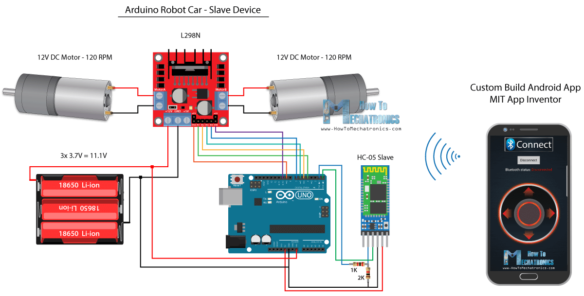
On the other hand, using the MIT App Inventor online application we will build our own Android app, and here’s how it looks.
So basically the app simulates a joystick, which appearance is made out of two images, or image sprites.
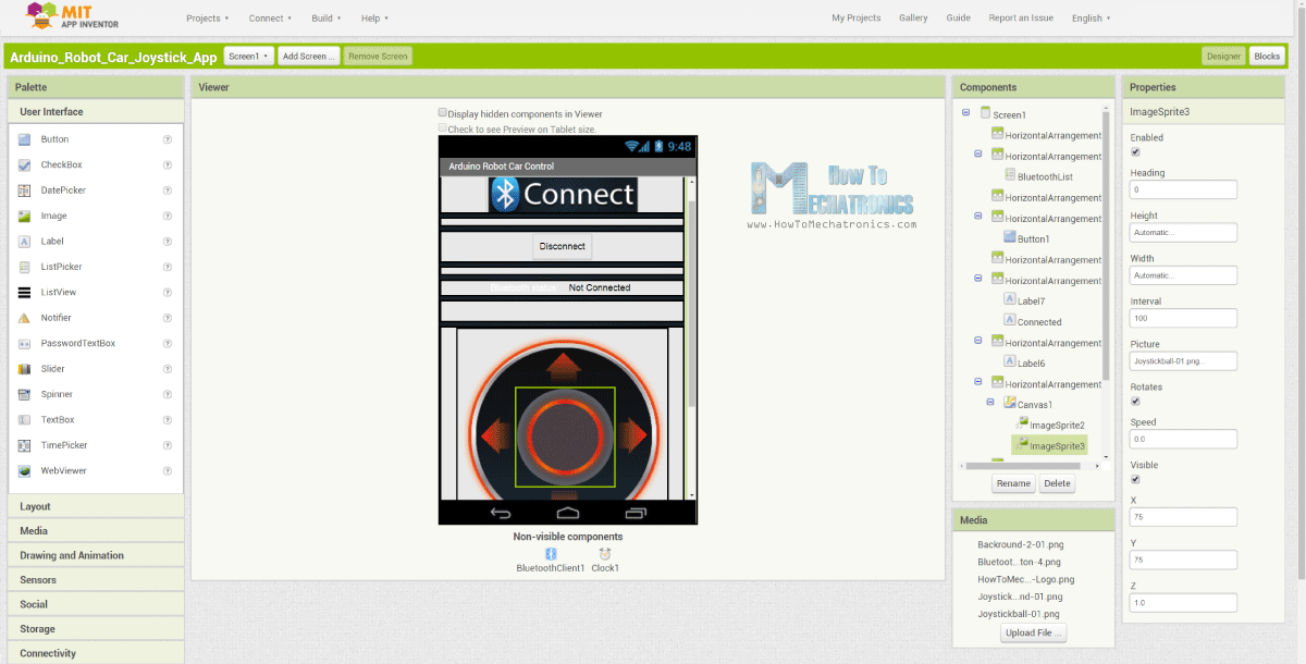
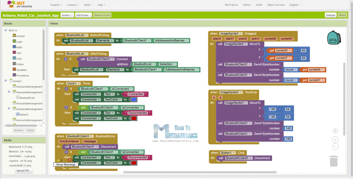
If we take a look at the blocks of this app, we can see that when the joystick sprite is dragged, the image of the joystick ball is moved to the current location of our finger, and at the same time we send the X and Y values over the Bluetooth to the Arduino car.
These values are accepted by the Arduino in the same way as in the previous example, using the Serial.read function.
// Read the incoming data from the Smartphone Android App
  while (Serial.available() >= 2) {
    x = Serial.read();
    delay(10);
    y = Serial.read();
  }Code language: JavaScript (javascript)
What we need to do additionally here is to convert the received X and Y values from the smartphone into the 0 to 1023 range, suitable for the motor control code below. These values depend of the canvas size, and the X and Y values I was getting from my app were from 60 to 220, which using the map() function I easily converted them.
// Makes sure we receive corrent values
  if (x > 60 & x < 220) {
    xAxis = map(x, 220, 60, 1023, 0); // Convert the smartphone X and Y values to 0 - 1023 range, suitable motor for the motor control code below
  }
  if (y > 60 & y < 220) {
    yAxis = map(y, 220, 60, 0, 1023);
  }Code language: JavaScript (javascript)
At the application blocks, we can also see that when the image sprite is touched up the joystick ball moves back to the center of the canvas and appropriate values are sent to the car in order stop moving. You can find and download this app on the website article, as well as, the two images of the joystick so you can build your own or modify this app.
Your can download the Android App below, as well as the two images for the joystick:
Complete Arduino code:
/*
   Arduino Robot Car Wireless Control using the HC-05 Bluetooth and custom-build Android app

             == SLAVE DEVICE - Arduino robot car ==

   by Dejan Nedelkovski, www.HowToMechatronics.com
*/

#define enA 9
#define in1 4
#define in2 5
#define enB 10
#define in3 6
#define in4 7

int xAxis, yAxis;
int  x = 0;
int  y = 0;

int motorSpeedA = 0;
int motorSpeedB = 0;

void setup() {
  pinMode(enA, OUTPUT);
  pinMode(enB, OUTPUT);
  pinMode(in1, OUTPUT);
  pinMode(in2, OUTPUT);
  pinMode(in3, OUTPUT);
  pinMode(in4, OUTPUT);

  Serial.begin(38400); // Default communication rate of the Bluetooth module
}

void loop() {
  // Default value - no movement when the Joystick stays in the center
  xAxis = 510;
  yAxis = 510;

  // Read the incoming data from the Smartphone Android App
  while (Serial.available() >= 2) {
    x = Serial.read();
    delay(10);
    y = Serial.read();
  }
  delay(10);

  // Makes sure we receive corrent values
  if (x > 60 & x < 220) {
    xAxis = map(x, 220, 60, 1023, 0); // Convert the smartphone X and Y values to 0 - 1023 range, suitable motor for the motor control code below
  }
  if (y > 60 & y < 220) {
    yAxis = map(y, 220, 60, 0, 1023);
  }

  // Y-axis used for forward and backward control
  if (yAxis < 470) {
    // Set Motor A backward
    digitalWrite(in1, HIGH);
    digitalWrite(in2, LOW);
    // Set Motor B backward
    digitalWrite(in3, HIGH);
    digitalWrite(in4, LOW);
    // Convert the declining Y-axis readings for going backward from 470 to 0 into 0 to 255 value for the PWM signal for increasing the motor speed
    motorSpeedA = map(yAxis, 470, 0, 0, 255);
    motorSpeedB = map(yAxis, 470, 0, 0, 255);
  }
  else if (yAxis > 550) {
    // Set Motor A forward
    digitalWrite(in1, LOW);
    digitalWrite(in2, HIGH);
    // Set Motor B forward
    digitalWrite(in3, LOW);
    digitalWrite(in4, HIGH);
    // Convert the increasing Y-axis readings for going forward from 550 to 1023 into 0 to 255 value for the PWM signal for increasing the motor speed
    motorSpeedA = map(yAxis, 550, 1023, 0, 255);
    motorSpeedB = map(yAxis, 550, 1023, 0, 255);
  }
  // If joystick stays in middle the motors are not moving
  else {
    motorSpeedA = 0;
    motorSpeedB = 0;
  }

  // X-axis used for left and right control
  if (xAxis < 470) {
    // Convert the declining X-axis readings from 470 to 0 into increasing 0 to 255 value
    int xMapped = map(xAxis, 470, 0, 0, 255);
    // Move to left - decrease left motor speed, increase right motor speed
    motorSpeedA = motorSpeedA - xMapped;
    motorSpeedB = motorSpeedB + xMapped;
    // Confine the range from 0 to 255
    if (motorSpeedA < 0) {
      motorSpeedA = 0;
    }
    if (motorSpeedB > 255) {
      motorSpeedB = 255;
    }
  }
  if (xAxis > 550) {
    // Convert the increasing X-axis readings from 550 to 1023 into 0 to 255 value
    int xMapped = map(xAxis, 550, 1023, 0, 255);
    // Move right - decrease right motor speed, increase left motor speed
    motorSpeedA = motorSpeedA + xMapped;
    motorSpeedB = motorSpeedB - xMapped;
    // Confine the range from 0 to 255
    if (motorSpeedA > 255) {
      motorSpeedA = 255;
    }
    if (motorSpeedB < 0) {
      motorSpeedB = 0;
    }
  }
  // Prevent buzzing at low speeds (Adjust according to your motors. My motors couldn't start moving if PWM value was below value of 70)
  if (motorSpeedA < 70) {
    motorSpeedA = 0;
  }
  if (motorSpeedB < 70) {
    motorSpeedB = 0;
  }
  analogWrite(enA, motorSpeedA); // Send PWM signal to motor A
  analogWrite(enB, motorSpeedB); // Send PWM signal to motor B
}Code language: PHP (php)
Arduino Robot Car Wireless Control Using NRF24L01 Transceiver Module
Now we can move on to the next method, wireless control of the Arduino robot car using the NRF24L01 transceiver modules.
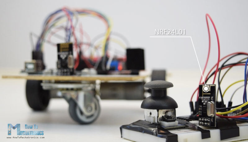
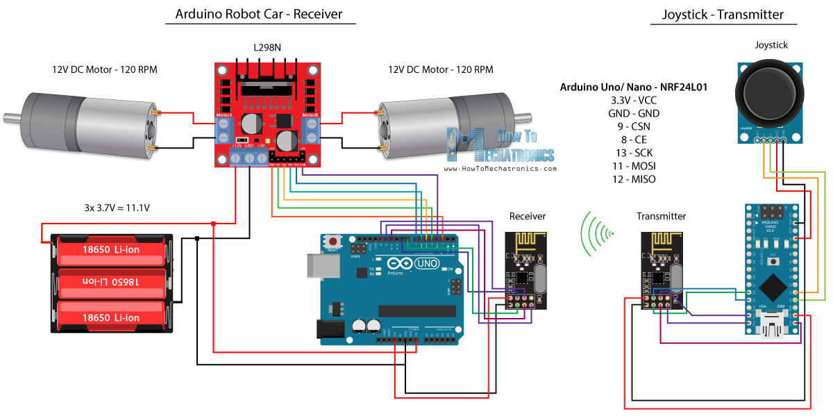
Here’s the circuit schematic. We can note that these modules use the SPI communication, so compared to the previous example, I had the move the Enable A and Enable B pins of the L298N driver to the pins number 2 and 3 of the Arduino board.You can get the NRF24L01 module on the following Amazon link.
Source Code
For this example we need to install the RF24 library. In a similar way to the previous example, after defining some pins and setting up the module as a transmitter, we read the X and Y values of the joystick and send them to the other NRF24L01 module at the Arduino robot car.
First we can note that analog readings are Strings, which using the string.toCharArray() function are put into a character array. Then using the radio.write() function we send that character array data to the other module.
Transmitter code:
/*
   Arduino Robot Car Wireless Control using the NRF24L01 Transceiver module

             == Transmitter - Joystick ==

   by Dejan Nedelkovski, www.HowToMechatronics.com

   Library: TMRh20/RF24, https://github.com/tmrh20/RF24/
*/

#include <SPI.h>
#include <nRF24L01.h>
#include <RF24.h>

RF24 radio(8, 9); // CE, CSN
const byte address[6] = "00001";

char xyData[32] = "";
String xAxis, yAxis;

void setup() {
  Serial.begin(9600);
  radio.begin();
  radio.openWritingPipe(address);
  radio.setPALevel(RF24_PA_MIN);
  radio.stopListening();
}

void loop() {

  xAxis = analogRead(A0); // Read Joysticks X-axis
  yAxis = analogRead(A1); // Read Joysticks Y-axis
  // X value
  xAxis.toCharArray(xyData, 5); // Put the String (X Value) into a character array
  radio.write(&xyData, sizeof(xyData)); // Send the array data (X value) to the other NRF24L01 modile
  // Y value
  yAxis.toCharArray(xyData, 5);
  radio.write(&xyData, sizeof(xyData));
  delay(20);
}Code language: PHP (php)
On the other side. at the Arduino robot car, after defining the module as receiver, we accept data using the radio.read() function. Then using the atoi() function we convert the received data, or the X and Y values from the joystick, into integer values, which are suitable for the motor control code below.
// Code from the Arduino Robot Car - NRF24L01 example

if (radio.available()) {   // If the NRF240L01 module received data
    radio.read(&receivedData, sizeof(receivedData)); // Read the data and put it into character array
    xAxis = atoi(&receivedData[0]); // Convert the data from the character array (received X value) into integer
    delay(10);
    radio.read(&receivedData, sizeof(receivedData));
    yAxis = atoi(&receivedData[0]);
    delay(10);
  }Code language: JavaScript (javascript)
It’s that simple, but of course as I already said, if you need more details how to connect and setup the modules, you can always check my particular tutorial for it.
Receiver code:
/*
   Arduino Robot Car Wireless Control using the NRF24L01 Transceiver module

             == Receiver - Arduino robot car ==

   by Dejan Nedelkovski, www.HowToMechatronics.com

   Library: TMRh20/RF24, https://github.com/tmrh20/RF24/
*/
#include <SPI.h>
#include <nRF24L01.h>
#include <RF24.h>

#define enA 2   // Note: Pin 9 in previous video ( pin 10 is used for the SPI communication of the NRF24L01)
#define in1 4
#define in2 5
#define enB 3   // Note:  Pin 10 in previous video
#define in3 6
#define in4 7

RF24 radio(8, 9); // CE, CSN
const byte address[6] = "00001";

char receivedData[32] = "";
int  xAxis, yAxis;

int motorSpeedA = 0;
int motorSpeedB = 0;

void setup() {
  pinMode(enA, OUTPUT);
  pinMode(enB, OUTPUT);
  pinMode(in1, OUTPUT);
  pinMode(in2, OUTPUT);
  pinMode(in3, OUTPUT);
  pinMode(in4, OUTPUT);
  Serial.begin(9600);
  radio.begin();
  radio.openReadingPipe(0, address);
  radio.setPALevel(RF24_PA_MIN);
  radio.startListening();
}

void loop() {

  if (radio.available()) {   // If the NRF240L01 module received data
    radio.read(&receivedData, sizeof(receivedData)); // Read the data and put it into character array
    xAxis = atoi(&receivedData[0]); // Convert the data from the character array (received X value) into integer
    delay(10);
    radio.read(&receivedData, sizeof(receivedData));
    yAxis = atoi(&receivedData[0]);
    delay(10);
  }

  // Y-axis used for forward and backward control
  if (yAxis < 470) {
    // Set Motor A backward
    digitalWrite(in1, HIGH);
    digitalWrite(in2, LOW);
    // Set Motor B backward
    digitalWrite(in3, HIGH);
    digitalWrite(in4, LOW);
    // Convert the declining Y-axis readings for going backward from 470 to 0 into 0 to 255 value for the PWM signal for increasing the motor speed
    motorSpeedA = map(yAxis, 470, 0, 0, 255);
    motorSpeedB = map(yAxis, 470, 0, 0, 255);
  }
  else if (yAxis > 550) {
    // Set Motor A forward
    digitalWrite(in1, LOW);
    digitalWrite(in2, HIGH);
    // Set Motor B forward
    digitalWrite(in3, LOW);
    digitalWrite(in4, HIGH);
    // Convert the increasing Y-axis readings for going forward from 550 to 1023 into 0 to 255 value for the PWM signal for increasing the motor speed
    motorSpeedA = map(yAxis, 550, 1023, 0, 255);
    motorSpeedB = map(yAxis, 550, 1023, 0, 255);
  }
  // If joystick stays in middle the motors are not moving
  else {
    motorSpeedA = 0;
    motorSpeedB = 0;
  }

  // X-axis used for left and right control
  if (xAxis < 470) {
    // Convert the declining X-axis readings from 470 to 0 into increasing 0 to 255 value
    int xMapped = map(xAxis, 470, 0, 0, 255);
    // Move to left - decrease left motor speed, increase right motor speed
    motorSpeedA = motorSpeedA - xMapped;
    motorSpeedB = motorSpeedB + xMapped;
    // Confine the range from 0 to 255
    if (motorSpeedA < 0) {
      motorSpeedA = 0;
    }
    if (motorSpeedB > 255) {
      motorSpeedB = 255;
    }
  }
  if (xAxis > 550) {
    // Convert the increasing X-axis readings from 550 to 1023 into 0 to 255 value
    int xMapped = map(xAxis, 550, 1023, 0, 255);
    // Move right - decrease right motor speed, increase left motor speed
    motorSpeedA = motorSpeedA + xMapped;
    motorSpeedB = motorSpeedB - xMapped;
    // Confine the range from 0 to 255
    if (motorSpeedA > 255) {
      motorSpeedA = 255;
    }
    if (motorSpeedB < 0) {
      motorSpeedB = 0;
    }
  }
  // Prevent buzzing at low speeds (Adjust according to your motors. My motors couldn't start moving if PWM value was below value of 70)
  if (motorSpeedA < 70) {
    motorSpeedA = 0;
  }
  if (motorSpeedB < 70) {
    motorSpeedB = 0;
  }
  analogWrite(enA, motorSpeedA); // Send PWM signal to motor A
  analogWrite(enB, motorSpeedB); // Send PWM signal to motor B
}Code language: PHP (php)
Arduino Robot Car Wireless Control Using HC-12 Long Range Transceiver
For the last method of wireless control of the Arduino robot car, we will use the HC-12 long range transceiver modules. These modules can communication to each other with distances up to 1.8 km.
The circuit schematic for this example is almost the same as the one for the HC-05 Bluetooth modules, as they are using the same method for communication with the Arduino, via the serial port.
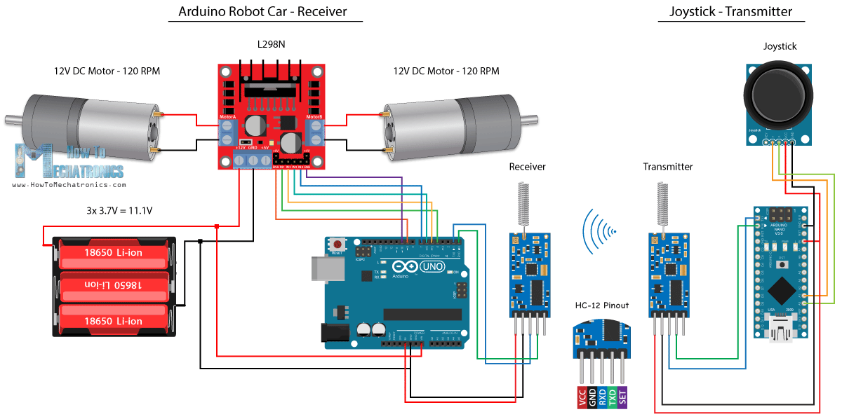
You can get the HC-12 Transceiver module on the following Amazon link.
Source Code
The Joystick code is exactly the same as the one for the Bluetooth communication. We just read the analog values of the joystick and send them to the other module using the Serial.write() function.
Transmitter code:
/*
   Arduino Robot Car Wireless Control using the HC-12 long range wireless module

                == Transmitter - Joystick ==

   by Dejan Nedelkovski, www.HowToMechatronics.com
*/

int xAxis, yAxis;

void setup() {
  Serial.begin(9600); // Default communication rate of the Bluetooth module
}

void loop() {
  xAxis = analogRead(A0); // Read Joysticks X-axis
  yAxis = analogRead(A1); // Read Joysticks Y-axis

  // Send the values via the serial port to the slave HC-05 Bluetooth device
  Serial.write(xAxis/4); // Dividing by 4 for converting from 0 - 1023 to 0 - 256, (1 byte) range
  Serial.write(yAxis/4);
  delay(20);
}Code language: JavaScript (javascript)
On the other side, with the while() loop we wait until the data arrive, then read it using Serial.read() function and convert it back into the 0 to 1023 range, suitable for the motor control code below.
Receiver code:
/*
   Arduino Robot Car Wireless Control using the HC-12 long range wireless module

             == Receiver - Arduino robot car ==

   by Dejan Nedelkovski, www.HowToMechatronics.com
*/

#define enA 9
#define in1 4
#define in2 5
#define enB 10
#define in3 6
#define in4 7

int xAxis, yAxis;
int  x = 0;
int  y = 0;

int motorSpeedA = 0;
int motorSpeedB = 0;

void setup() {
  pinMode(enA, OUTPUT);
  pinMode(enB, OUTPUT);
  pinMode(in1, OUTPUT);
  pinMode(in2, OUTPUT);
  pinMode(in3, OUTPUT);
  pinMode(in4, OUTPUT);

  Serial.begin(9600); // Default communication rate of the Bluetooth module
}

void loop() {
  // Default value - no movement when the Joystick stays in the center
  xAxis = 510;
  yAxis = 510;

  // Read the incoming data from the
  while (Serial.available() == 0) {}
  x = Serial.read();
  delay(10);
  y = Serial.read();
  delay(10);

  // Convert back the 0 - 255 range to 0 - 1023, suitable for motor control code below
  xAxis = x * 4;
  yAxis = y * 4;

  // Y-axis used for forward and backward control
  if (yAxis < 470) {
    // Set Motor A backward
    digitalWrite(in1, HIGH);
    digitalWrite(in2, LOW);
    // Set Motor B backward
    digitalWrite(in3, HIGH);
    digitalWrite(in4, LOW);
    // Convert the declining Y-axis readings for going backward from 470 to 0 into 0 to 255 value for the PWM signal for increasing the motor speed
    motorSpeedA = map(yAxis, 470, 0, 0, 255);
    motorSpeedB = map(yAxis, 470, 0, 0, 255);
  }
  else if (yAxis > 550) {
    // Set Motor A forward
    digitalWrite(in1, LOW);
    digitalWrite(in2, HIGH);
    // Set Motor B forward
    digitalWrite(in3, LOW);
    digitalWrite(in4, HIGH);
    // Convert the increasing Y-axis readings for going forward from 550 to 1023 into 0 to 255 value for the PWM signal for increasing the motor speed
    motorSpeedA = map(yAxis, 550, 1023, 0, 255);
    motorSpeedB = map(yAxis, 550, 1023, 0, 255);
  }
  // If joystick stays in middle the motors are not moving
  else {
    motorSpeedA = 0;
    motorSpeedB = 0;
  }

  // X-axis used for left and right control
  if (xAxis < 470) {
    // Convert the declining X-axis readings from 470 to 0 into increasing 0 to 255 value
    int xMapped = map(xAxis, 470, 0, 0, 255);
    // Move to left - decrease left motor speed, increase right motor speed
    motorSpeedA = motorSpeedA - xMapped;
    motorSpeedB = motorSpeedB + xMapped;
    // Confine the range from 0 to 255
    if (motorSpeedA < 0) {
      motorSpeedA = 0;
    }
    if (motorSpeedB > 255) {
      motorSpeedB = 255;
    }
  }
  if (xAxis > 550) {
    // Convert the increasing X-axis readings from 550 to 1023 into 0 to 255 value
    int xMapped = map(xAxis, 550, 1023, 0, 255);
    // Move right - decrease right motor speed, increase left motor speed
    motorSpeedA = motorSpeedA + xMapped;
    motorSpeedB = motorSpeedB - xMapped;
    // Confine the range from 0 to 255
    if (motorSpeedA > 255) {
      motorSpeedA = 255;
    }
    if (motorSpeedB < 0) {
      motorSpeedB = 0;
    }
  }
  // Prevent buzzing at low speeds (Adjust according to your motors. My motors couldn't start moving if PWM value was below value of 70)
  if (motorSpeedA < 70) {
    motorSpeedA = 0;
  }
  if (motorSpeedB < 70) {
    motorSpeedB = 0;
  }
  analogWrite(enA, motorSpeedA); // Send PWM signal to motor A
  analogWrite(enB, motorSpeedB); // Send PWM signal to motor B
}Code language: PHP (php)
So that’s pretty much everything for this tutorial. Feel free to ask any question in the comments section below.
Hello Dejan, Thanks for this awesome project. Even 5 years later it is still a great help.
Please could you provide the MIT App Inventor aia file. Unfortunately the link above seems broken and links to the apk file.
Many thanks!
Hi, I have updated the download file. Please take try one. If the change doesn’t appear clear the browser cache or use different web-browser. Cheers
Hello Dejan
I really enjoy your tutorials, and have built many of these projects with great success. Maybe you can help with a minor issue I’m having with my wireless NRF24L01 robot car. Every so often, the x and y axis get interchanged – that is, moving the joystick forward and reverse turns the car left and right, and so on. I have to switch the transmitter off and back on to correct. Any idea how to correct this glitch?
Many thanks!
Steve S.
Hey, glad to hear that. Well I would suggest to check my DIY Arduino RC Transmitter project. I have the same example there for controlling the NRF24L01 robot car but with a bit different code in regard to the radio communication, or sending and receiving the date.
Thanks, Dejan!
Will do.
-Steve
Thank you so much for the tutorials, i have made RC car using Hc-12 module based on your code and schematic, it worked fine in one go thanks,
But there are few issues-
1. to turn left or right, only one side motors run and other side motor should move in opposite direct but keeps standing. Please suggest how to modify the code, i want while turn it left one side motors run forward and other backward.
2. When car goes away from the HC-12 module range it keeps running, doesn’t stop, keeps moving and had to catch it to stop it or have to come near to car with remote.
3. my HC-12 module signal quality is far better than NRF24, but it also give few mtrs range of about 10-20mtrs only, please suggest how to do it.
4. need to add few lights that can be controlled by remote, please suggest to modify the code.
Thanks in Advance.
Sanjay
Hey, glad you to hear you made the project successfully.
Well if you want to both wheels to turn opposite when turning left or right you need to modify the code in the “move left” and “move right” “if” statements sections. For example, for moving right, you will need to set / change the rotation direction of the left motor using the “in1” and “in2” pins, and vice versa.
For preventing the car running when you lose signal, you can add a code that tells all movements to stop if there is no communication between the modules. Check my Arduino RC Transmitter project, I used this method there, so you will find explanation how you can do that.
As for the range of the HC-12 module, for getting the farthest communication distance, you need to set the baud rate of the module to the lowest level.
Adding few LEDs to the project should be quite easy. Controlling them is light turning a single pin on and off.
Cheers!
Thank you so much for your reply
Thanks Dejan,
Would request if you can send me code to add in to stop the car when signal is lost, i am trying many ways but could not succeed.
Hello Mr. Dejan,
Big fan of yours. Thanks so much for the article.
I am having a little bit difficulty with the Bluetooth. My HC-05 has a default baud rate of 9600. I changed the code and uploaded. The pairing also works. However, it appears no values are being sent from the app to the bluetooth. I tried to do a serial.println inside the serial.available loop – no values.
Any suggestions? I have spent good amount of time trying to figure this out.
Thanks again,
Chris
Can I use higher rpm DC motors? And what do the pwm number correlate to? I would have to change those if I got a 550 rpm motor correct?
Sure, you can use higher rpm DC motors. The PWM value is used to control motors speed from 0 to 100% of its capability. The Arduino accepts PWM values from 0 to 255 which correspond from 0 to 100 power or rpm.
Thank you! I’m going to start this project soon. I plan to add 2 more dc motors later to make it 4wd. Hopefully I can do it. Thank you again!
Will it work with a power bank instead of batteries
Well the powerbank has 5V output, while the this DC motor driver works at 12V. Maybe you can make it working with a powerbank if using different driver or/ and DC motors.
Dear Dejan,
Thank you for this usefull article. I had followed all steps for HC-12 part, but I have a strange problem, about Motor A, it moves only in one direction if joystick is pulled up and the motor has no movement in other direction when you put the joystick to down. I guessed it maybe related to faulty joystick so I have changed the it, but the problem stills. Even I had changed the motor. The strange part appears when if you move the joystick rapidlly, the direction of motor A will be changed and still has no movement when joystick in down. Maybe it related to PMW function, I don’t know.
Generic ARD-A000067 Arduino Mega 2560 Rev3 – Made in Italy
Can I use this Arduino board for making this application or the one you have mentioned in the links???
You can use any Arduino board.
Hi,
I have made your arduino car and very much like it. I am trying to get the app to connect with the bluetooth module but it is having problems. I have one difference with the car I have created, I have used the HM-10 BLE Bluetooth 4.0 (MLT-TB05) rather than the HC05 just because I had it available. Other than that I have used the exact same as you including the app you created on MIT app inventor 2.
I have been able to pair my phone with the bluetooth module and can open the app in the MIT AI2 companion fine. However I cannot connect to the module inside the app, I keep receiving “Error 507: Unable to Connect. Is device turned on?” when I try to connect to it.
I have tried changing the band for communications to 115200, which I understand is the MLT-TB05’s communication frequency but it doesn’t seem to work on either 9600, 38400 or 115200. It may be a firmware issue but I am unsure how to check this or update.
Have you any ideas on how I can get the two to connect?
P.S. I am a big fan of yours and wish to teach my high school students how to make any and all of your projects. It astounds me your knowledge of electronic engineering and the things you have made. I want to make this project with my year 10’s but I need to make sure the price for all the components is under $10 Australian and I’d need to buy the gearboxes, motor driver and bluetooth module at least to do the project (we can laser print the rest and they have an arduino and batteries already).
Hey, thank you, I’m so glad to hear you find my projects interesting and want to teach the students with them.
I haven’t used the HC-10 BLE module, neither I have one to try it and see how it works. So at this moment I cannot help you much, sorry about that.
Hello! Thank you so much for this tutorial, I am hoping to use it for my Engineering class. I have followed your schematic, uploaded your code to the arduino, downloaded the app, and I can’t get it to work properly. I can connect to the Bluetooth module just fine, but when I use the joystick I get almost no response. I can get 1 motor to move sometimes, and even then it is always in the same direction.
Any ideas what might be causing this? I went line by line through the code multiple times, triple checked the circuit, so I think the issue might be the app but I struggle to understand how to use MIT app inventor 2. I tried modifying your app but I can’t get it to work. Any ideas what the issue might be and how to solve it?
Hey, it sounds like you have a problem with the Bluetooth communication. Try to change the baud rate, your HC-05 module might have a default baud rate of 9600. Try to print the incoming data from the Bluetooth onto the Serial monitor and see what kind of values are you getting.
First i would like to thank you,having tried at least 5 other similar projects without great results i found yours for the NRFL which worked first time every time( I’ve built 3 now). My grandkids would like to race them is there a way to set each pair (controller and tank) to their own channel so they do not interfere with each other ?.
Thank you.
I’m glad to hear that. Well yes that’s possible, but please check the RF24 library documentation you should fine more details on that topic there, currently I don’t have such an example.
can i try it into 4 wheels?
Sure, with some little tweaks on the code.
but i keep on getting some error like “could not fit 259 into 1 byte” what should i do? thanks
Hello, I’m working on my project which is wireless controll via bluetooth. I’ve watched your video on youtube. I’m also using h bridge and 12v power supply. What should i do to prevent may arduino and h bridge safe specially IC thanks
Hey, well if the H-bridge module works on 5V then you are safe to use it with the Arduino, while powering the Arduino through the Vin pin (12V to Vin pin) or the power jack.
Great project, Is there any reason why i could not use Arduino Nano’s or Micro’s as controllers for both sides of the project’s?
Keep up the good work and thanks for sharing
Thanks! Sure you can use those Arduino boards.
Thanks alot for the great work.
but im facing a problem
i connected everything as u told us, but one most is not working and the other one is only moving 2 or 3 degrees.. i barely hear its sound and keeps giving me this message on the app
“could not fit 259 into 1 byte”
is the a solution
That error indicates that when you are sending a value of 259 to the Arduino, which more then one byte. You can notice that in the App we sent only 1 byte to the Arduino, so values from 0 to 255 can be sent. In case you want to send bigger value it can’t fit in 1 byte. So should make sure you send only values lower then 255, you have to somehow confine the are of the joystick in the app, or adjust those values you get when touching the area of the joystick.
@shady I changed the baud rate from 38400 to 9600 and it worked perfectly
Hey!
If I change the transmission input to an accelerometer instead of the joystick, using the hc-12 as the communication device, how do I need to change the transmission code for the same ?
Thanks!
Well you need to read the accelerometer data and in the same way send that data to the receiver. Of course, the code would depend on the accelerometer model, however you can check my MEMS accelerometer tutorial which explains how to use accelerometer with Arduino.
Hey,
I was trying to make this car. In the blocks of the MIT app inventor, you subtract Current X and Current Y by 64(When ImageSprite is dragged). You also subtract 140 from 64 (When ImageSprite is TouchUp). You also send 140(Send1ByteNumber).
Can you explain what these things mean?
Thanks!
Hey, the canvas size is something around 130px, so in order to position it in the middle of the screen, I need to subtract half of its values, because the X,Y values for positioning are in the upper left corner of the canvas.
Thanks!
You’ve helped me a lot through your tutorials on Arduino!
Keep it up!
Does the Nano have to be plugged in via USB to have power? If so, how else could we power it so that we can carry the remote around and not rely on having a laptop connection? (Sorry if this is a dumb question, I’m really new to Arduino and electronics and this is one of my first projects.)
You can use a battery to power the Arduino. There is a “Vin” pin on the Arduino which can be supplied with voltage from 7.2v to 12V. That’s the same connection as the power jack, those 12V would pass through the on-board voltage regulator which will make it 5V suitable for the Arduino.
Hi there thanks for the hard work i want to build the car that is controlled via a smartphone using bluetooth and i actually built everything according to the tutorial but there is a problem with the app when i try to stop the motor it does not stop and the motors are going at one high speed if you can help me solve this problem i would be very grateful
thx
Hey, the problem is probably in the smartphone app. When releasing the app joystick, the app should send right values so that the motors stop spinning, just as explained.
Hi there,
I would like to build my own robot car with smarthphone. I downloaded the app and i build the robotcar with the right circuit schematic. I connected to the HC-05 and I touched to the Joystick ball and nothing happen. Sometimes i hear some noise from the motor and sometimes it has run, but only one way and only 1 motor. In your video you talk about canvas size. Where can i see that?
Do you have any idea how can I solve that?
Thanks
Well you might need to adjust the canvas size. This adjustment should be done in the app blocks. First you should check what values you are getting from the area where you touch on your phone and then make sure that they match with the values for driving the motors.
Any idea of how I can determine the values coming out of my canvas area? I am guessing that the 64 in “get currentx – 64” and the “140-64” values have to be changed…right?
I used a Samsung note3 and have the same problem as Benjamin.
Thanks.
Yes, that’s right.
how can you check what values you get from your phone?
Print the values, the data variable, on the serial monitor, using the Serial.println function.
Thank you very much
i was planning to make the code for something similar and now i saved a lot of time
Thanks for sharing all these 🙂
Ps : As i had never used before MIT App Inventor if the project file was available would be more easy to experiment based in your build and learn to use this aplication
i am saying these because i saw that in other projects you make the project files available.
i subscribed to your youtube channel… i think you deserve more subscribers than the number you have until now.. i think you will have them soon 🙂
I’ve just updated the article and added the .aia project file as a download file for this project. Thanks for the support!
Thanks a million bro. You have saved a lot of other’s time and helped so that we can make more advance thinigs
Don’t we need any libraries for hc-12
No, we are simply using the serial communication.
thanks a lot works great