In this tutorial I will show you how I converted my DIY 3D Printed SCARA robot arm that I built in one of my previous videos to work as a laser engraver. You can watch the video following video or read the article below.
Project Overview
The SCARA robot has 4 degrees of freedom which are driven by 4 NEMA 17 stepper motors and controlled using an Arduino board. In the original video I used an Arduino UNO board in combination with a CNC Shield, but now we will use an Arduino MEGA board in combination with a RAMPs board. We need this combination because we will use the Marlin 3D Printer firmware for controlling the robot.
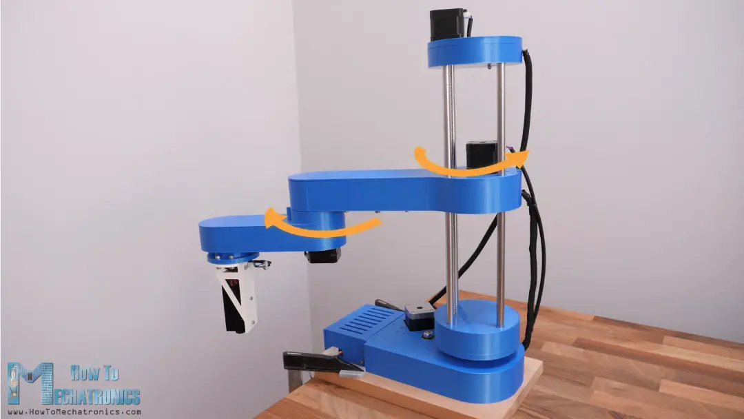
As for the mechanical part, I just had to change the gripper mechanism with a laser module. In this case, I’m using 5.5W laser module which is good enough for engraving.
A cool feature that we get with this SCARA robot setup is that we can have a bigger range of the Z-axis movement and so we can laser engraver taller objects.
Also, the working area is pretty impressive considering the small footprint of the robot. It can use the area in front of it as well as on both sides. We can actually set it up to use almost the entire 360 degrees around the robot as a working area. We can do that thanks to the open-source Marling 3D printer firmware which has options for laser engraving and SCARA robot setup.
For generating the G-codes I’m using yet another open-source software, Inkscape and a plugin for it called Inkscape-Lasertools. We can generate G-codes with contours only or with contours and infill from the same vector image, and we have various options like adjusting the laser beam, travel speed, infill speed, perimeter speed, laser on and off commands including PWM control of the laser and so on.
Nevertheless, now I will walk you through the entire process of setting up a SCARA robot to work as a laser engraver. We will take a look at the design of this SCARA robot, how to install and configure the Marlin firmware according to our machine, and how to prepare the drawings and the G-codes for engraving. So, let’s get started.
Design and 3D Model
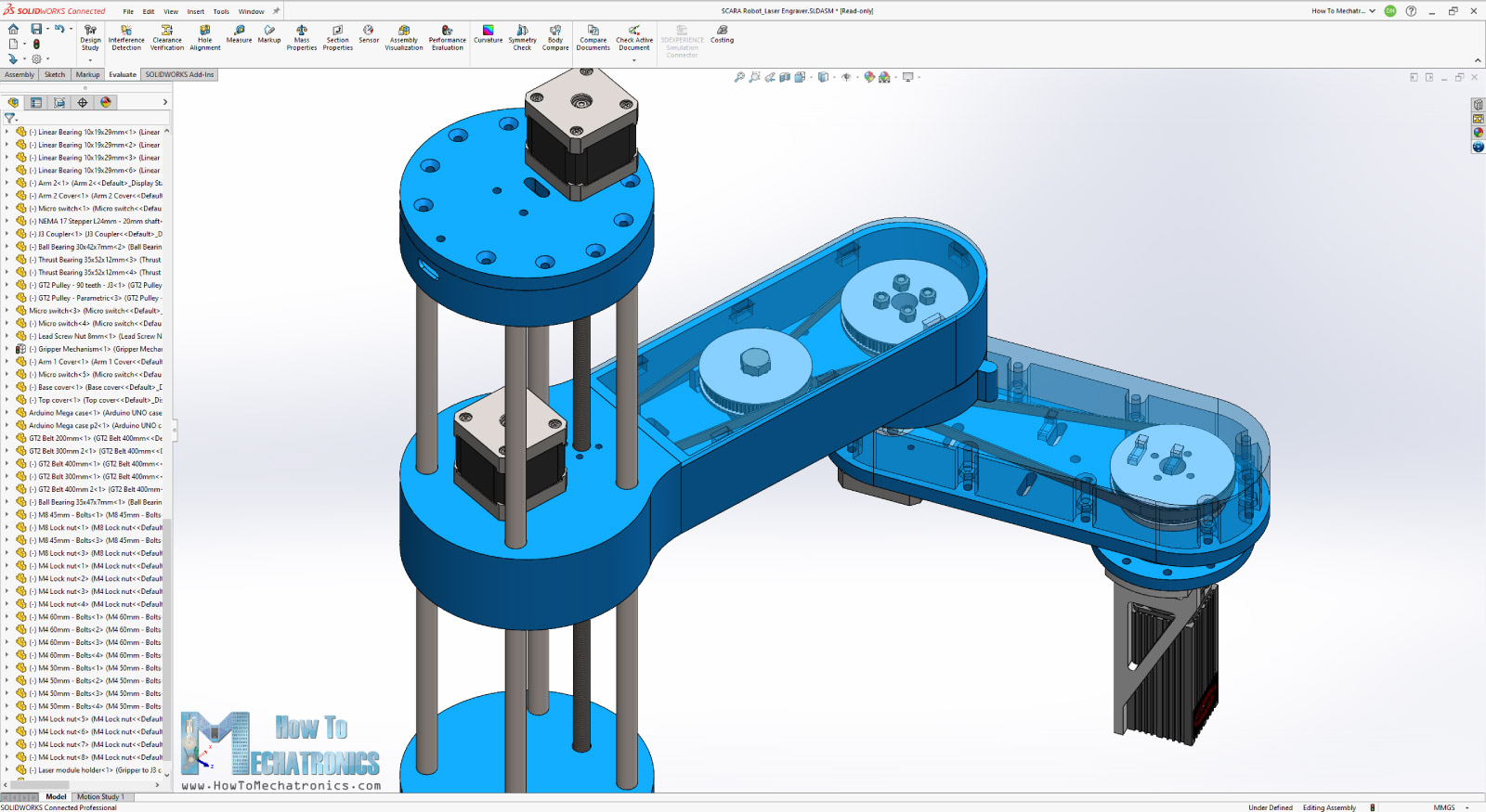
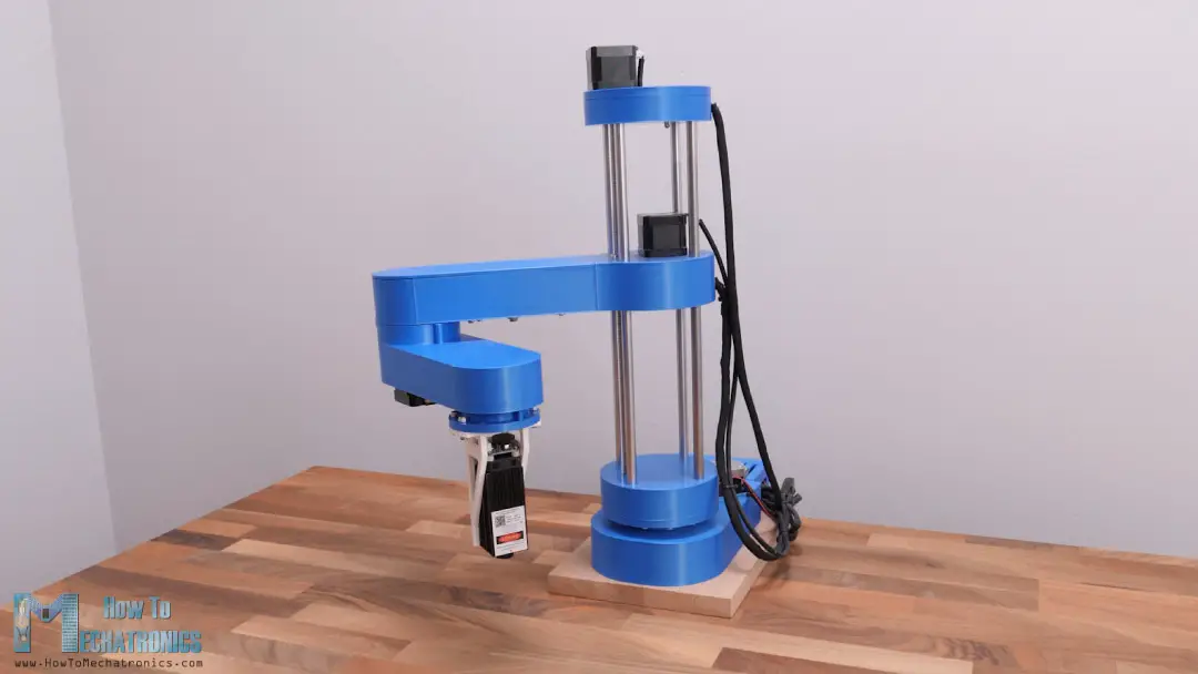
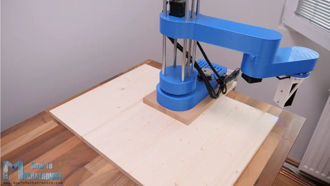
Here’s a quick look at the 3D model of this SCARA robot so you can see how it works in case you haven’t watched the original tutorial where I explain in details how I built it.
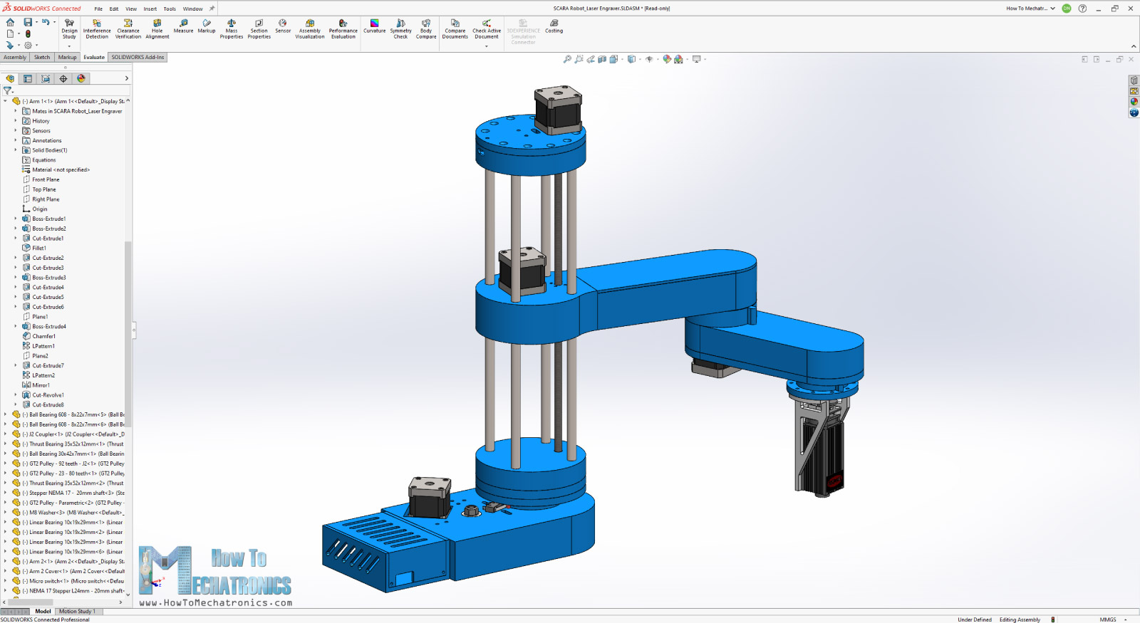
The robot is designed in a way that most of the parts can be easily 3D printed. The joints are driven by NEMA 17 stepper motors which speed is reduced with the help of GT2 belts and some suitable 3D printed GT2 pulleys. The robot has 4 degrees of freedom, but in this case, we only need 3 DOF, two rotations for reaching any point in the work area and one linear motion for adjusting the height of the laser.
3D Model and STL Download Files
You can get this 3D model, as well as the STL files for 3D Printing from Cults3D.
Sponsored
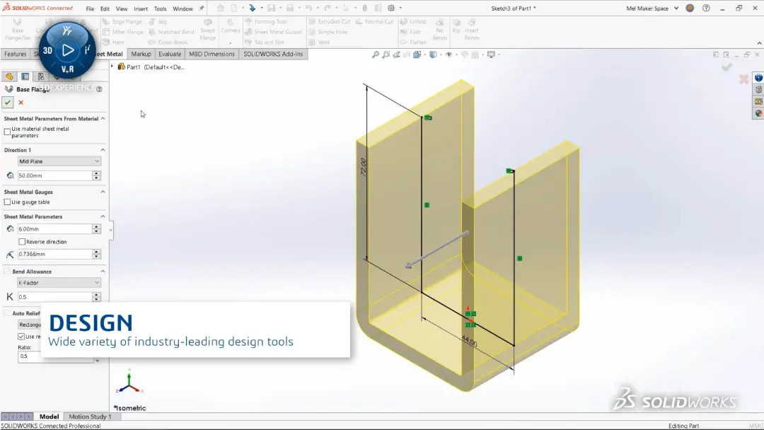
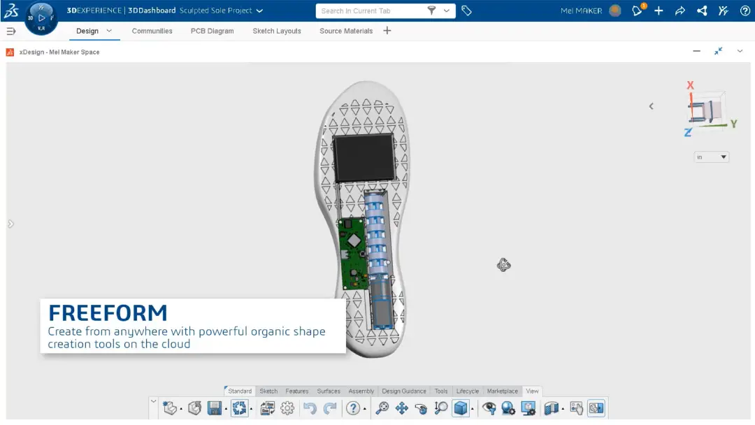
I designed this SCARA robot using 3DEXPERIENCE SOLIDWORKS for Makers which is also the sponsor of this video. Yes, you heard it right. With 3DEXPERIENCE SOLIDWORKS for Makers, SOLIDWORKS is finally bringing their industry-leading design tools to makers of all kinds at an insanely low price.
Makers can now access the best SOLIDWORKS design tools for only $99 a year, but for MY viewers, SOLIDWORKS is providing a limited time offer that will get you these tools for even cheaper!
That’s right. For viewers of this video, you can get this bundle today – which includes a cloud connected version of SOLIDWORKS, as well as browser-based design tools like 3D Creator and 3D Sculptor – at a special 20% off price while supplies last!
All you have to do is click my following link and create your free 3DEXPERIENCE ID, which will allow you to access this special 20% off offer – so you can start making with the best today. Big thanks to SOLIDWORKS for sponsoring and supporting education content like this.
Check out SOLIDWORKS for makers
Installing the Laser Module
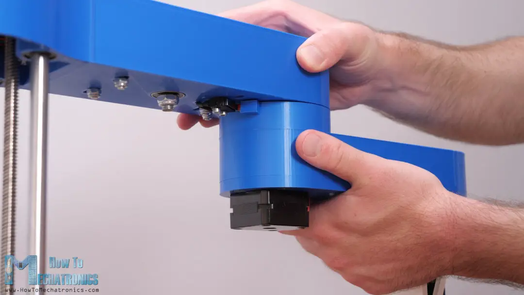
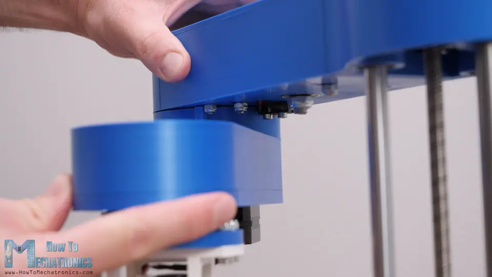
First, I removed the gripper mechanism from the robot which was held in place with four bolts.
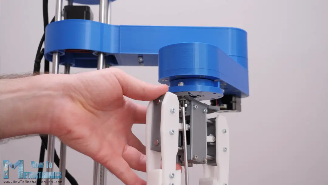
The wires used for controlling the gripper servo will be now used for controlling the laser module.
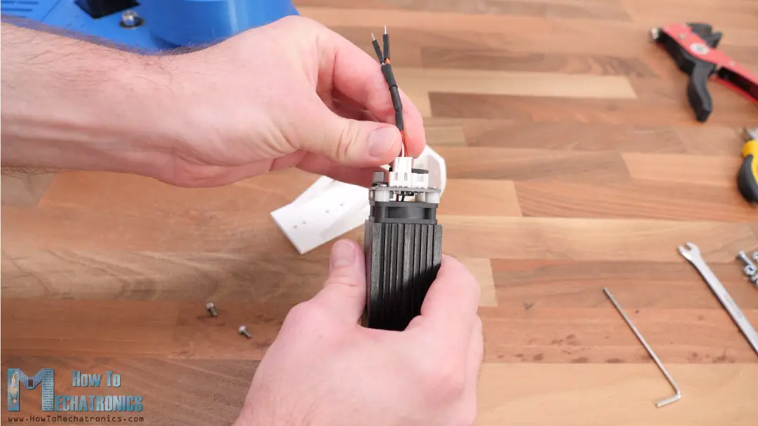
The particular laser module that I have works at 12V and can be controlled using PWM signal with just two wires, Ground and VCC. For connecting the laser, I used the connector that comes with the module, the one with the 3 pins. The left black wire is Ground and the middle, the white wire in my case is the VCC. I soldered two male jumper wire connectors to these wires so I can easily connect them to the wires for the end effector.
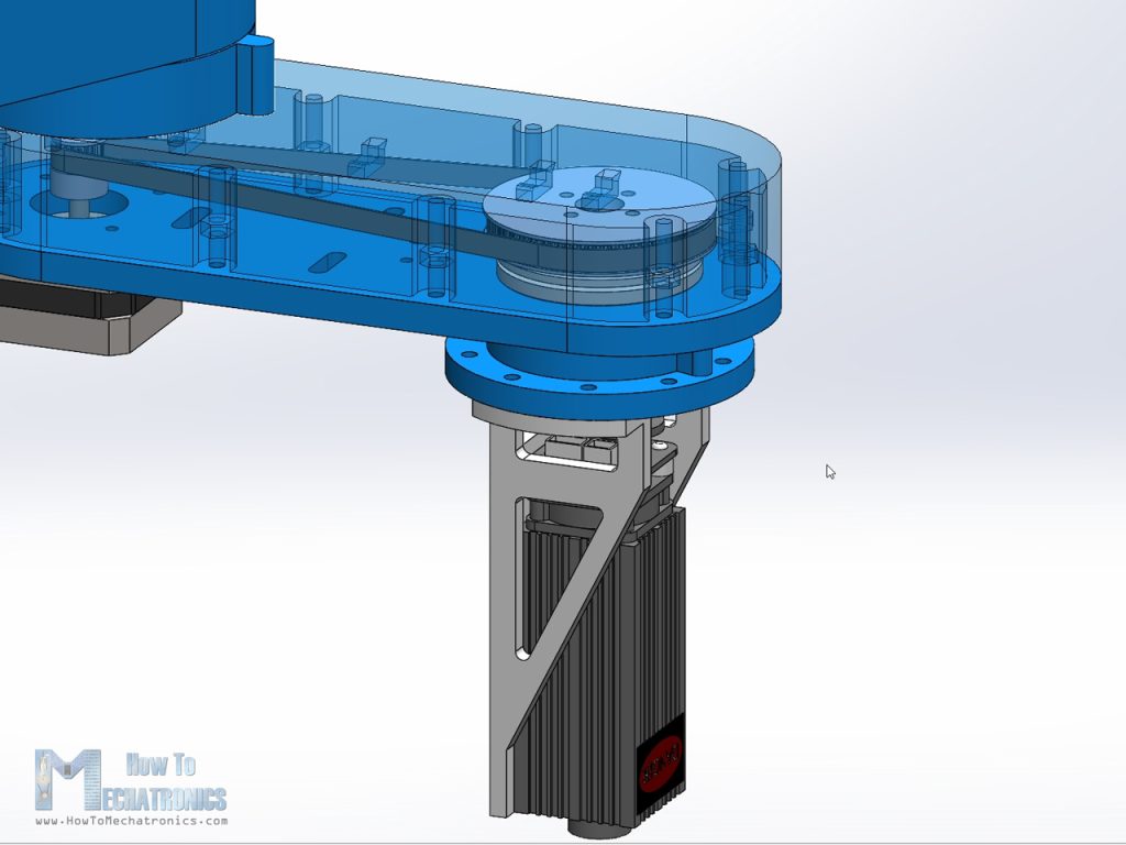
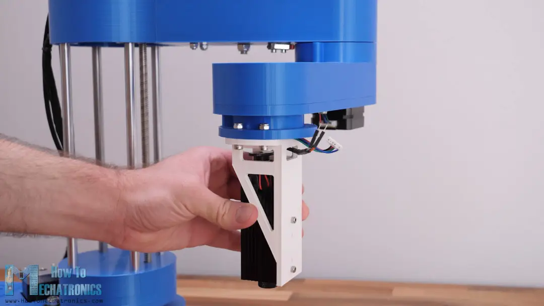
Then I simply put the connector in place, pass the wire through one of the openings of the holder, and secured the laser module with two M3 bolts. Using four M4 bolts I secured the laser module to the robot.
Next, as I mentioned earlier, instead of the Arduino UNO board that I used for controlling the robot in the original video, now we need an Arduino MEGA board and combination with a RAMPS board.
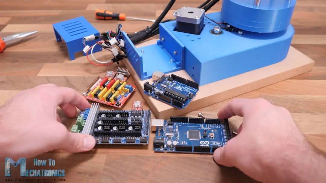
Here first we need to select the step resolution of the drivers. Of course, for smoother motion we should select the highest possible resolution by adding three jumpers for each stepper driver. I’m using the A4988 stepper driver which has 16th step resolution, but we can also use the DRV8825 stepper driver which has 1/32 step resolution.
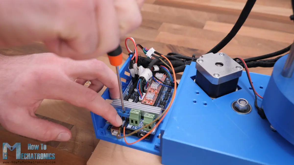
Then we can connect all the wires in place. I had all my wires marked so I don’t mess them up.
SCARA Robot Laser Engraver Circuit Diagram
Here’s the circuit diagram of how everything needs to be connected.
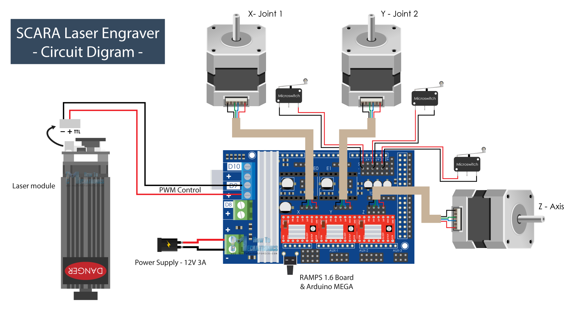
The steppers motors go right above the drivers and the limit switches which are Normally Closed with two wires go at the endstops S and – pins for each axis respectively.
For controlling the laser module, we will use the pin D9 which in a 3D printer setup is used for controlling a fan. This pin is PWM capable so we can control the intensity of the laser with it. For powering everything we need 12V power supply with minimum current rate of 3A.
You can get the components needed for this project from the links below:
- Stepper Motor – NEMA 17……………… Amazon / Banggood / AliExpress
- A4988 Stepper Driver…………………..… Amazon / Banggood / AliExpress
- RAMPS 1.6 Board………………………..… Amazon / Banggood / AliExpress
- Arduino MEGA………………….…..……… Amazon / Banggood / AliExpress
- Limit Switch …………………………………. Amazon / Banggood / AliExpress
- DC Power Supply …………………………. Amazon / Banggood / AliExpress
- Laser Module ………………………………… Amazon / Banggood / AliExpress
- Laser Safety Goggles …………………….. Amazon / Banggod / AliExpress
Disclosure: These are affiliate links. As an Amazon Associate I earn from qualifying purchases.
As for the mechanical components, you can check the original article.
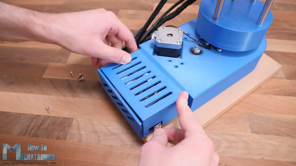
Once I connected everything as explained, I squeezed a little bit the wires and covered electronics so that everything looks nice and clean.
Finishing the assembly
There’s one more thing that I needed to change on my SCARA robot so that it works properly, and that’s to change the when the second arm limit switch is triggered. As the SCARA robot will be set to work as right-handed, the homing of the second arm needs to be at 0 degrees, or in line with the first arm, while being able to rotate to the left. For that purpose, I simple glued a small piece to the arm joint so that it triggers the limit switch at the described position.
Actually, there’s one more small detail that I needed to change. The original limit switch trigger was interfering with one of the nuts at the bottom of the arm so the arm couldn’t reach its full motion.
I simple removed that nut, replaced it with threaded insert so that when securing back the part in place it won’t stick out.
And that’s it. The SCARA robot is now ready to work as a laser engraver, but of course, first we need to install the firmware to the Arduino board.
See Also: DIY Arduino Robot Arm with Smartphone Control
Marlin Firmware for Laser Engraving with SCARA Robot
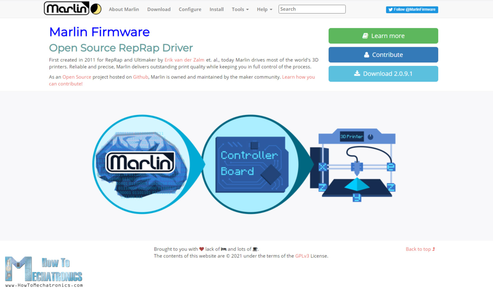
As I said, I will use the Marlin firmware which is one of the most-widely used open-source firmware for 3D printers, which also has options for laser engraving and SCARA robot setups. We can download the Marlin firmware either from its official website or Github.com.
To install the Marlin firmware to the Arduino MEGA board we will use PlatformIO IDE instead of Arduino IDE. As the Marlin firmware is big and complex, the Arduino IDE might sometimes give errors and not be able to compile it.

PlarformIO is built on top of the Visual Studio Code editor, and it can be installed as extension to it. This means, first we need to install Visual Studio Code, then search for the PlatformIO in the extension manager and install it from there.

Once the installation is done, we can click the Open Project button, navigate to the Marlin folder that we downloaded and unzipped, and click “Open Marlin”.
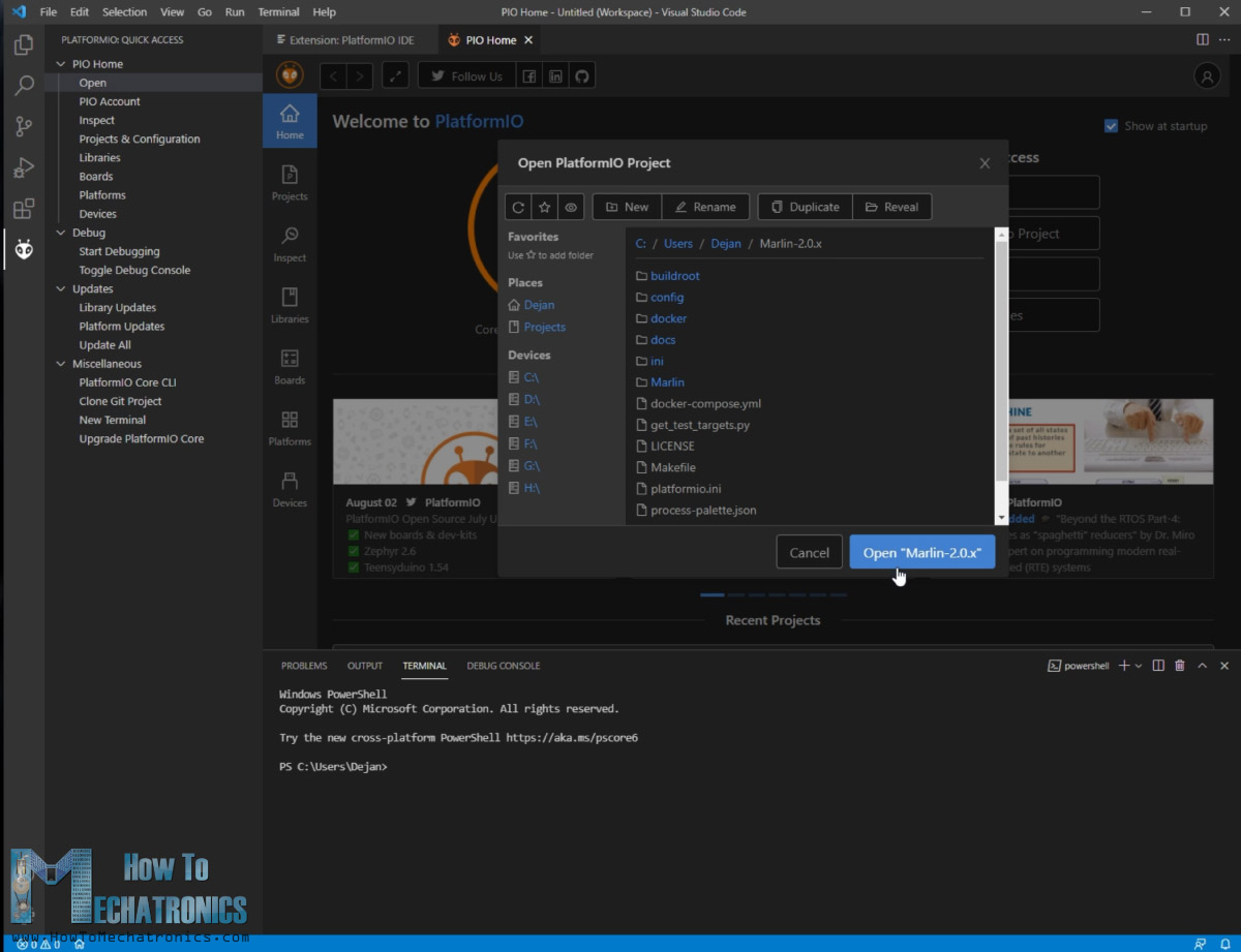
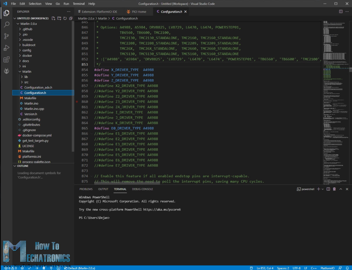
This will load all Marlin files into the editor and so we can open and edit them. The two main files where we do all the adjustments according to our machine setup are the Configuration.h and Configuration_adv.h files.
Actually, before we open the Marlin folder, we should first go to the Configuration repository on Github.com from where we can download some pre-tested configuration files which are suitable for us. In the “Examples” folder we should go to the “SCARA” folder and copy these two configuration files and paste them into our Marlin folder.
See also: How to Setup GRBL & Control CNC Machine with Arduino
Configuring the Marlin Firmware
So, once we re-open the Marlin folder with the “SCARA” configuration files, we can open the Configuration.h file and edit some parameters according to our machine. The first thing here is to select the type of SCARA robot we have.
/**
* MORGAN_SCARA was developed by QHARLEY in South Africa in 2012-2013.
* Implemented and slightly reworked by JCERNY in June, 2014.
*/
//#define MORGAN_SCARA
/**
* Mostly Printed SCARA is an open source design by Tyler Williams. See:
* https://www.thingiverse.com/thing:2487048
* https://www.thingiverse.com/thing:1241491
*/
#define MP_SCARA
#if EITHER(MORGAN_SCARA, MP_SCARA)
// If movement is choppy try lowering this value
#define SCARA_SEGMENTS_PER_SECOND 100
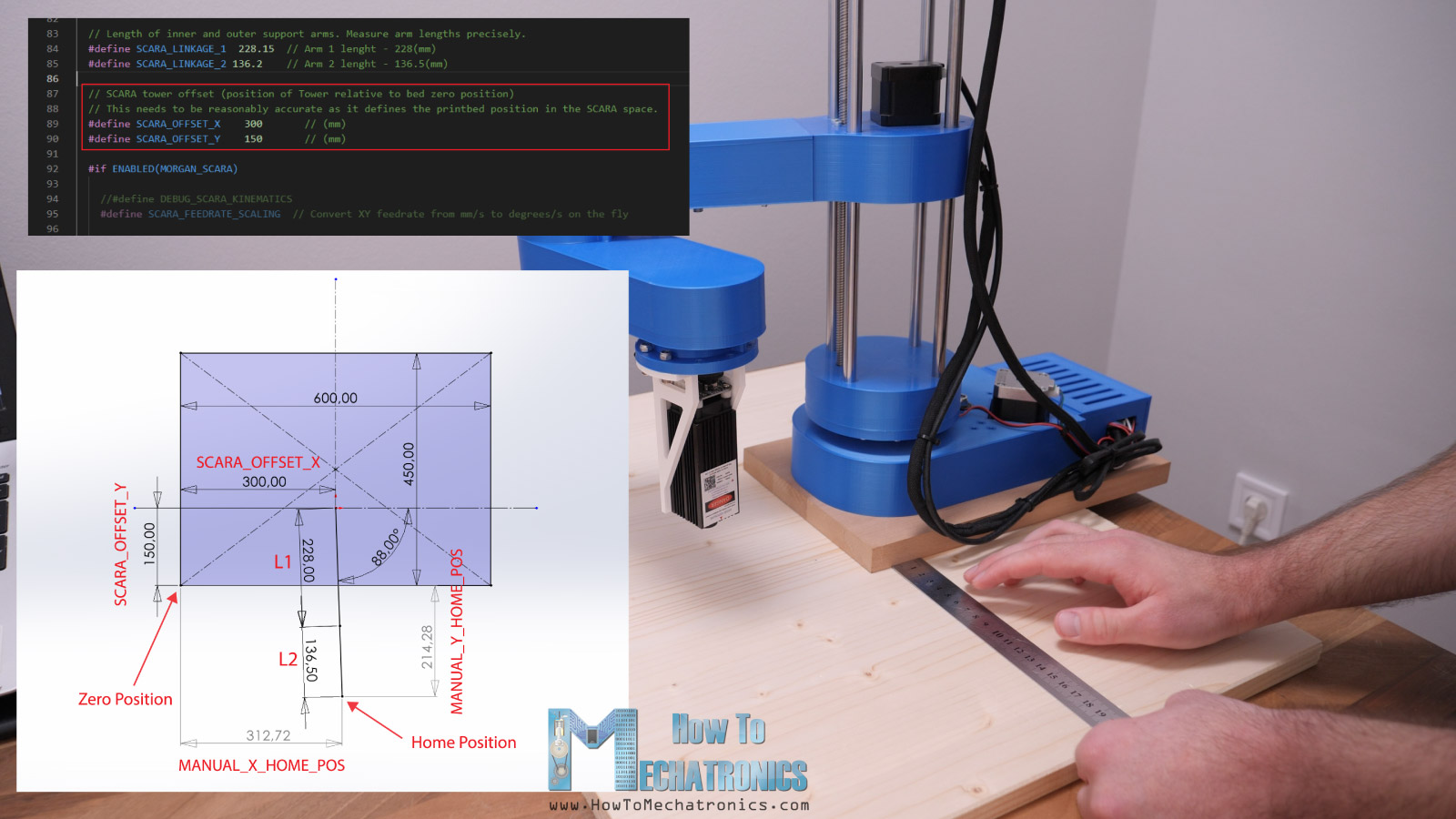
// Length of inner and outer support arms. Measure arm lengths precisely.
#define SCARA_LINKAGE_1 228.15 // Arm 1 lenght - 228(mm)
#define SCARA_LINKAGE_2 136.2 // Arm 2 lenght - 136.5(mm)
// SCARA tower offset (position of Tower relative to bed zero position)
// This needs to be reasonably accurate as it defines the printbed position in the SCARA space.
#define SCARA_OFFSET_X 300 // (mm)
#define SCARA_OFFSET_Y 150 // (mm)Code language: Arduino (arduino)The “MORGAN_SCARA” is for parallel SCARA robot and the “MP_SCARA” is for serial SCARA robot, just like the one we have. This is based on an open-source design by Tyler Williams which implements inverse kinematics on the G-codes generated for normal cartesian systems.
In my previous tutorial I already explained what is inverse kinematics and how it works with this SCARA robot so for more details you can check that tutorial out. Briefly, with inverse kinematics we calculate at what angles the two arms should position in order to reach a given X, Y coordinate. The math behind the inverse kinematics is based on trigonometry, and the result depends solely on the lengths of the two arms.
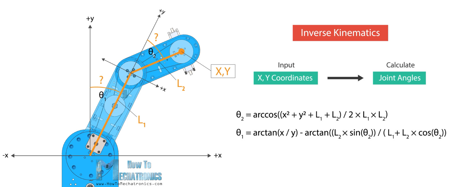
That being said, here we need to enter the length of the robot arms, and in this case that’s 228mm for the first arm and 136.5mm for the second arm. The next parameter that we need to set is the zero position of the work bed. This value is entered with the SCARA_OFFSET_X and Y values and it’s the distance from the tower or the first joint relative to the to the bed zero position.
There’s one more set of parameters that we need to adjust according to our machine, and that’s the MANUAL_X_HOME_POS for both X and Y. These values are the X and Y distances from the robot arm end effector or the laser when it’s in home position, relative to the bed zero position that we previously set. In order to get these values, I made a simple sketch in SOLIDWORKS with the two lines representing the two arms of the SCARA robot.
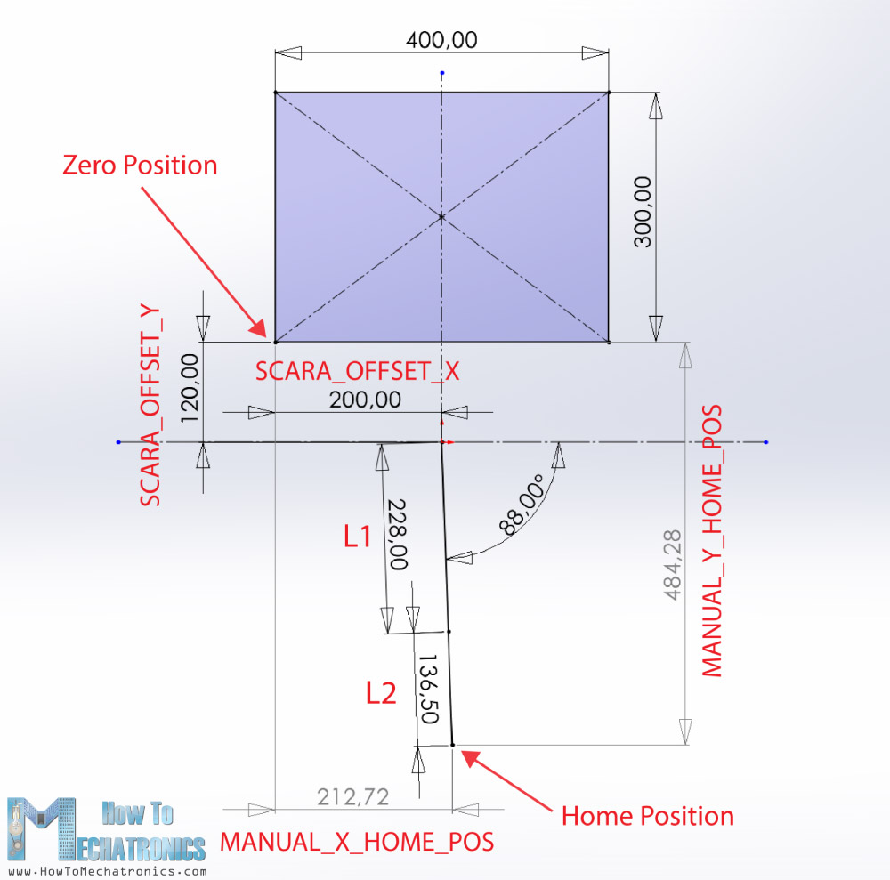
From here can set the desired bed zero position, and get the values for the MANUAL_X_HOME_POS variables.
Next, we need to define the endstop connectors. In our case we have one endstop for each axis, which is at minimum position.
#define USE_XMIN_PLUG
#define USE_YMIN_PLUG
#define USE_ZMIN_PLUGCode language: Arduino (arduino)
In addition to that, we need to define X_HOME_DIR to –1 which indicate the direction of the endstops when homing.
// Direction of endstops when homing; 1=MAX, -1=MIN
// :[-1,1]
#define X_HOME_DIR -1
#define Y_HOME_DIR -1
#define Z_HOME_DIR -1Code language: Arduino (arduino)
Here we should also check whether all __MIN_ENDSTOP_INVERTING variables are set to “FALSE”.
Then we need to adjust the DEFAULT_AXIS_STEPS_PER_UNIT values to match with our machine.
#define DEFAULT_AXIS_STEPS_PER_UNIT { 177.7777777, 142.2222222, 400, 93 }Code language: Arduino (arduino)These values indicate how many steps the program should send to the stepper drivers in order motor to move one unit, and in this case that’s rotation of the joint of one degree. Here’s how I calculated these values for my SCARA robot.
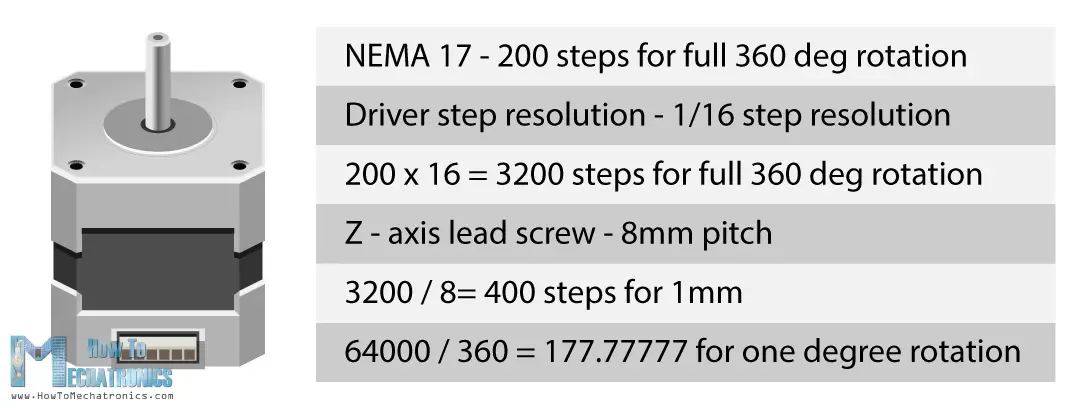
The NEMA 17 stepper motors take 200 steps for full rotation, but as we are using 16th step resolution, that means we need to send 3200 steps to the driver in order to motor to make full 360 degrees rotation. In addition to that, for the first joint we have 20:1 speed reduction, which means we need 64000 steps for full rotation. If we divide this value with 360, we will get the number 177.777, which is actually the number of steps that the program needs to send to the driver in order to rotate the joint one unit or one degree.
The second arm has 16:1 speed reduction so the value will be 142.222. For the Z axis we have a lead screw with 8mm pitch, which means one full rotation of the motor will results in 8mm linear monition. One unit here is one mm, so we need to divide the 3200 steps by 8, and so we get the value of 400, which is the number of steps needed for the Z axis to move one unit or one mm. The fourth value here is for the extruder stepper, but as we don’t have any extruder here, we don’t have to change it.
The stepper motor direction depends on the way we have connected the wires. In case we have it wrong, we can either reverse the wires or change it here in software by setting the INVERT_X_DIR variables to TRUE.
// Invert the stepper direction. Change (or reverse the motor connector) if an axis goes the wrong way.
#define INVERT_X_DIR false
#define INVERT_Y_DIR false
#define INVERT_Z_DIR falseCode language: Arduino (arduino)
We should do few more changes in order to get this Marlin firmware working. As Marlin is primarily firmware for classical cartesian style printers, the SCARA mode that it features, has some small bugs which weren’t solved yet at the time I as making this project. Here’s are the changes that I did in order to get it working.
In scara.cpp, line 75 I replaced MORGAN_SCARA with MP_SCARA. In motion.cpp, I had to comment the line 1716 and 1717, in cofiguration.h comment VALIDATE_HOMING_ENDSTOPS, and in configuration_adv.h uncomment QUICK_HOME.
Actually, even with these changes, the homing was still not working 100% properly but I will explain the workaround I used to get the it working.
Nevertheless, now we can click the Upload button located at the bottom left of the editor and the Marlin firmware will be installed to the Arduino board. You download this particular Marlin firmware with all changes that I made to work with this SCARA robot below or of course, you can download the original Marlin firmware from Github.com and make all changes on your own as I explained.
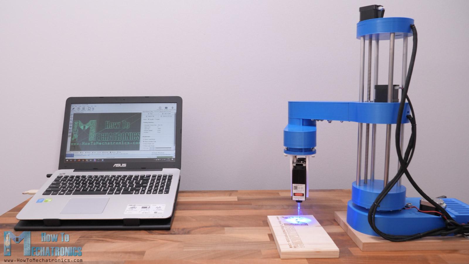
Control Software – Rapetier-host
All right, so once we have the Marlin firmware installed, now we need a computer program for controlling robot and sending G-codes to it. There are many options, but I chose to use Rapetier-host which is a popular 3D Printing software. We can download and use this software for free. Once we install it, we can go to Config > Printer Settings and adjust several things here.
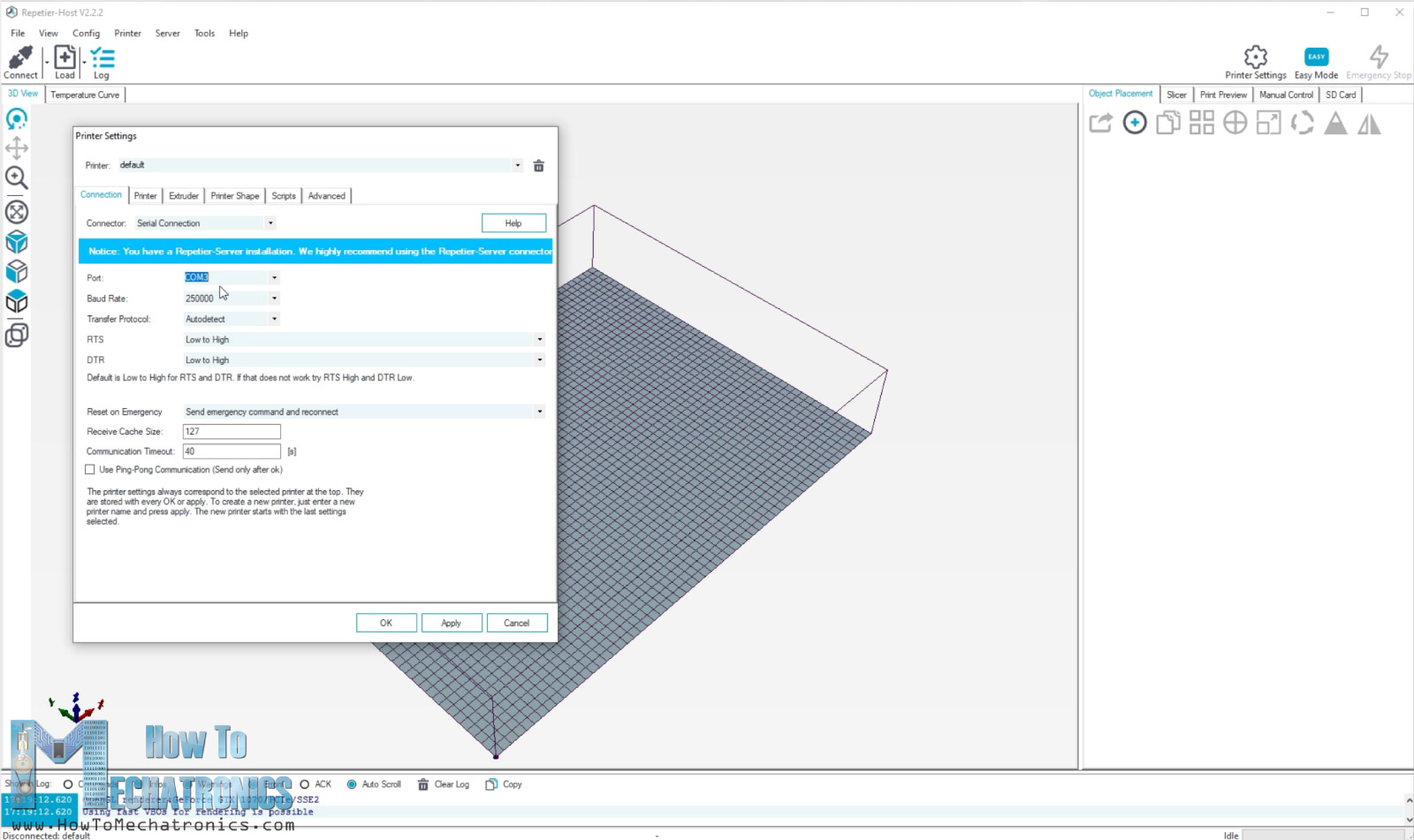
We should select the COM port to which our Arduino is connected and select the Baud Rate which we set in the Marlin firmware. In the Printer Shape tab, we should set the X and Y max values and the Printer Area.
Once we apply these settings, we can click the Connect button and the software should connect to our SCARA robot. Then we can go in the Manual Control tap and from here try to move the printer.
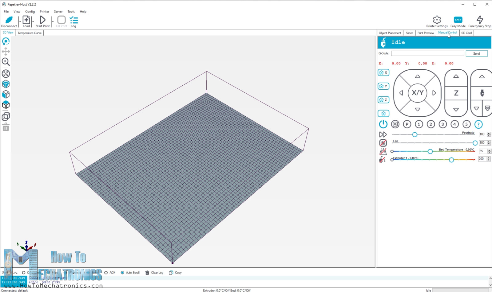
Note that when pressing the X or Y arrows, the robot might behave weird as it implements inverse kinematics right away, and will probably move both arms even if pressed only one arrow.
Nevertheless, in order to get the robot working, we should first home it. Before we click the home button, we should manually bring the joints closer to the limit switches.
When we click the Home button, the robot should start moving towards the limit switches. Actually, the second arm will start moving towards its limit switch while the first arm should move opposite. Once the second arm or the Y axis will hit its limit switch, the first arm or the X axis will then start moving toward its limit switch as well. Once the X limit switch is reached, the robot will go for the Z limit switch.
So, after the homing is done, we should be able to start engraving or manually move the robot around the its working area. However, if we try to do anything right away, for some reason the robot will misbehave and it will do strange movements. To avoid this strange behavior, after the homing we just have to disconnect the robot from the software and then re connect it again.
Now we can manually move or engrave and the robot will work properly. This is probably a bug in the Marlin firmware, and it’s there because the SCARA mode in this firmware is not backed well as there is no much interest in it.
Nevertheless, if we send the G-code command G00 X0 Y0 the robot should go to its zero position, the one that we set in the Marlin Configuration.h file.
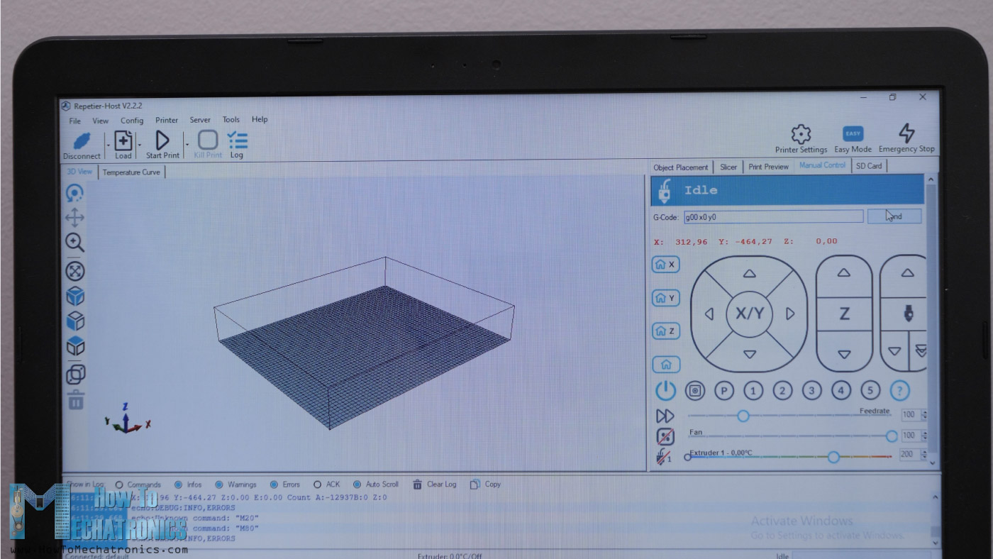
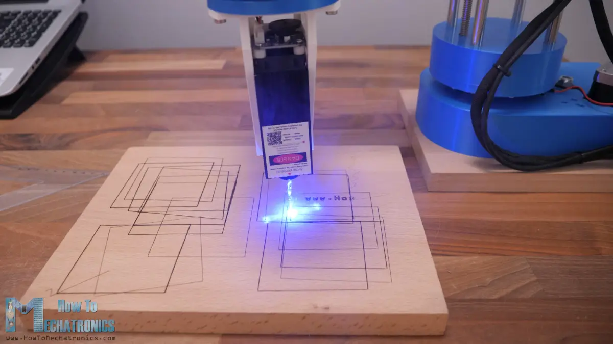
Then we can active the laser by sending the M106 S10 command. The value behind S can be from 0 to 255 and it’s actually the PWM control of the laser power from 0 to 100%. So, we are using a value of S10 here so that it won’t burn anything but it will be visible so we can see the zero position and also adjust the focus of laser.
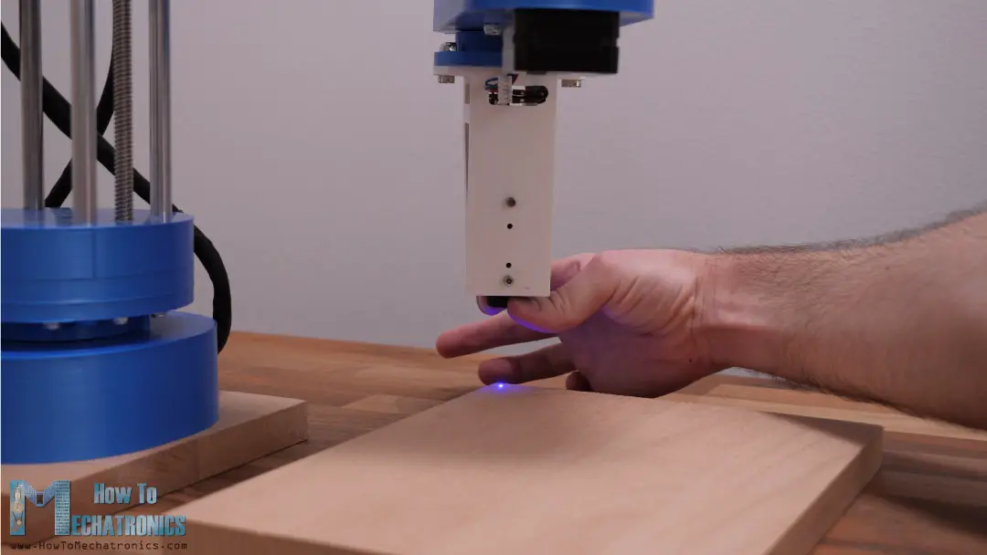
The focus can by manually adjust by rotating the laser lens at the bottom and at the same time it depends on the distance between it and the working piece. It’s recommended to set a distance of around 5cm and adjust the focus till you get the smallest dot possible.
Laser Engraving with the SCARA Robot
In order to calibrate the machine, it’s good idea to start with engraving a simple square shape so we can see whether it works properly.
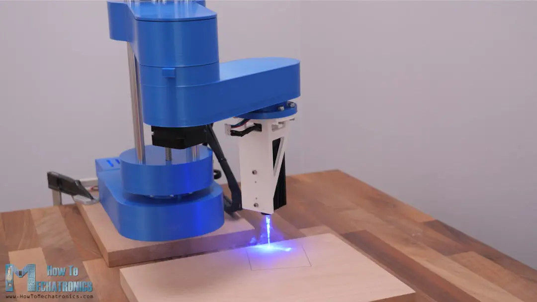
In my first try, the square shape was not in the right position and orientation and that’s because I have set a wrong value for the MANUAL_X_HOME_POS variable. Once I corrected it, the square shape came out close to what it should be.
So, I load up a G-code of my logo, and set the robot to engrave it.
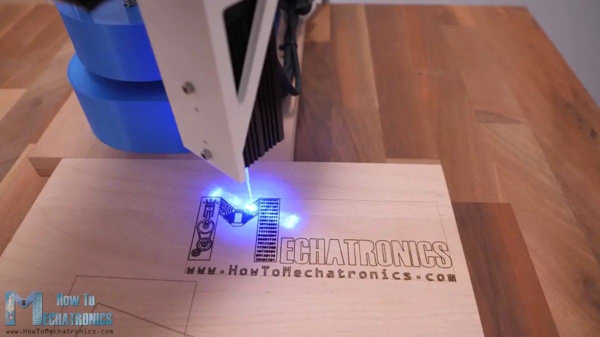
To be honest, looking at this SCARA robot working as laser engraver is so cool, but please note that we MUST use laser safety goggles that will protect our eyes from the ultraviolet light of the laser, as it’s very dangerous. Also, we should use a safety respirator mask and work in open space or well-ventilated room, as the fumes produced while laser engraving are also dangerous for our health.
Nevertheless, the logo engraving came out well, but I noticed that it wasn’t totally square.
So, I got back to engraving the simple square shape in order to find out what was causing the problem. I realized that the problem is with the dimensions for the lengths of the arms. As the robot is not that rigid, when the arms are extended the weight of the arms themself make the robot lean a little forward. This causes the actual dimension or position of the arms to be a little bit off.
After making dozens of tests, I ended up adjusting the values for the lengths from 228 to 228.15mm for the first arm, and from 136.5 to 136.2mm for the second arm. This gave me the most accurate result and now the square shape was right. Though, depending on the location of printing, whether the arm is fully extended or not, the accuracy could still vary.
Generating G-code for Laser Engraving
Lastly, let me show you how I prepared the drawings and generated G-codes for laser engraving them. I used Inkscape for that purpose which an open-source vector graphics software.
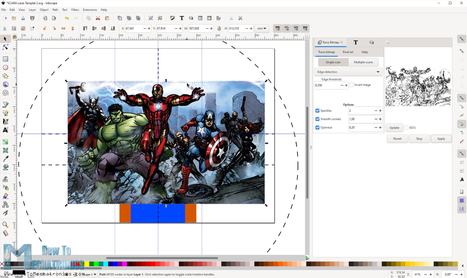
Here first we need to set the page size to the size of our working area. As an example, I will show you how I prepared the Arduino logo for laser engraving.
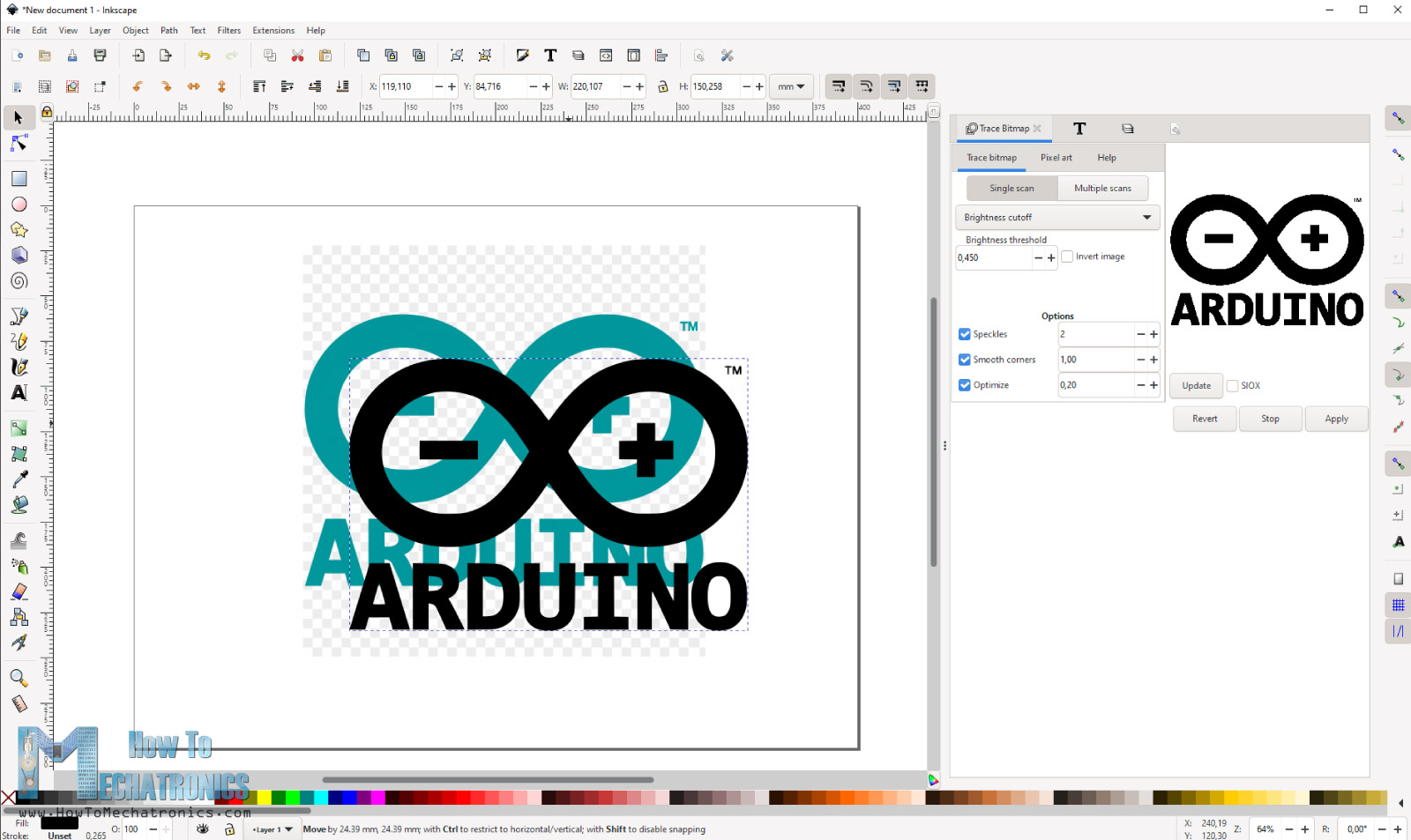
I downloaded an image of the Arduino logo and imported into Inkscape. Using the Trace Bitmap function, first we need to convert the image into a vector format. We can only generate G-codes from vector shapes and for that purpose I used a plugin called Inkscape-Lasertools. We can download this plugin from Github.com and we can install it by copying the files from the zip file, and pasting them into the Inkscape extensions directory.
So, once we have the plugin installed, we can go to Extensions>Lasertools to open it and use it to generate a G-code. There are several options to set and adjust with this plugin. As we connected our laser to the D9 pin which is used for controlling a fan, we can activate the laser by sending the M106 command.
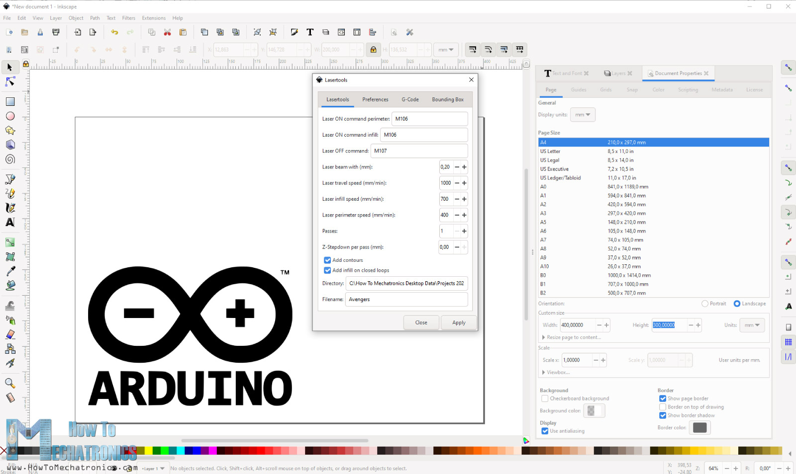
We can choose whether the G-code will only contain the contours of the shape or the infill on closed loops as well. We can set the Laser travel speed, the laser infill speed and the perimeter speed.
When choosing an infill, if we want to lower the intensity of the laser in the infill area, we can add PWM value to the M106 command to set the laser intensity, for example, M106 S128 for 50% laser power. We could achieve similar effect if we leave the laser power to 100% but increase the travel speed in the infill area. So, these are actually settings that we should play with to see what works best for us.
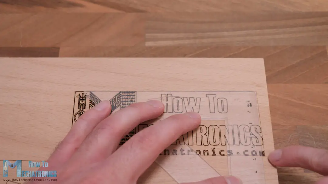
In the Preferences tap we can select “Remove tiny infill paths”, and in the Bounding Box tab we can select “Generate G-Code for bounding box preview”. This feature is very useful as it generates a preview G-code of the area where the drawing will take place, and so we can position our working piece precisely.
Ok, so once we generate the G-code we can load it in Repetier-Host program. As this is not 3D printing, but just travel moves, we should select the check box “Show Travel Moves” to preview our G-code.
We can finally click the “Print” button and our SCARA robot will laser engrave the work piece. I already said, watching this SCARA robot laser engraving is so satisfying and we can laser engrave so many things with it.
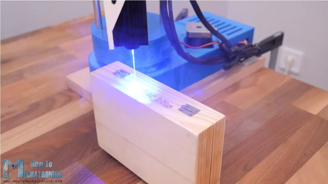
A good feature is that it has adjustable Z-axis which means we can laser engrave taller objects, like for example, this wooden box for my Forstner bits. I engraved my logo on the front, and a text “Forstner bits” on the back of the box.
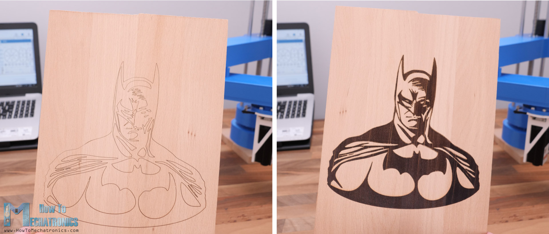
Here’s an example of engraving the same vector shape, a batman silhouette in this case, with just contours and with infill on closed loops.
Of course, when engraving with infill the time needed to finish the job is much longer but also the final appearance is much better.
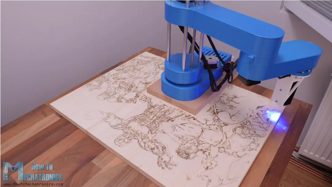
Finally, let me show you how I engraved this huge drawing with area of 600x450mm with this SCARA robot.

I placed the robot on top of the work piece so it can reach the front and the two sides. I manually adjusted the work piece and the robot to be in middle and parallel to each other.
In the Marlin firmware I set the zero position to be at the bottom left corner of the work piece, which is 300mm away from the robot in X direction and 150mm in Y direction. We should mind the signs when defining these values. According to this I also changed the MANUAL_X and Y_HOME_POS variables.
After uploading the firmware with these new values, I homed the robot as explained earlier and send the laser to zero position. Then I activated the laser, so I can further adjust the work price orientation of needed.
By sending G01 commands, which do straight lines I could check and adjust the work piece to be position properly.
Now as for preparing the G-code for this engraving I made a template of with this configuration of the work piece and the robot in Inscape. From here I can see where the robot can reach with the laser and according to it modify the drawing.
For the drawing, I downloaded an image and converted to vector image by using the Trace Bitmap tool.
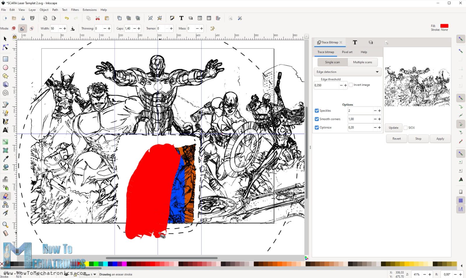
Then I rescaled and position the image as I wanted, and using the Erase tool I deleted the areas where the robot is and the area which is outside the robot reach.
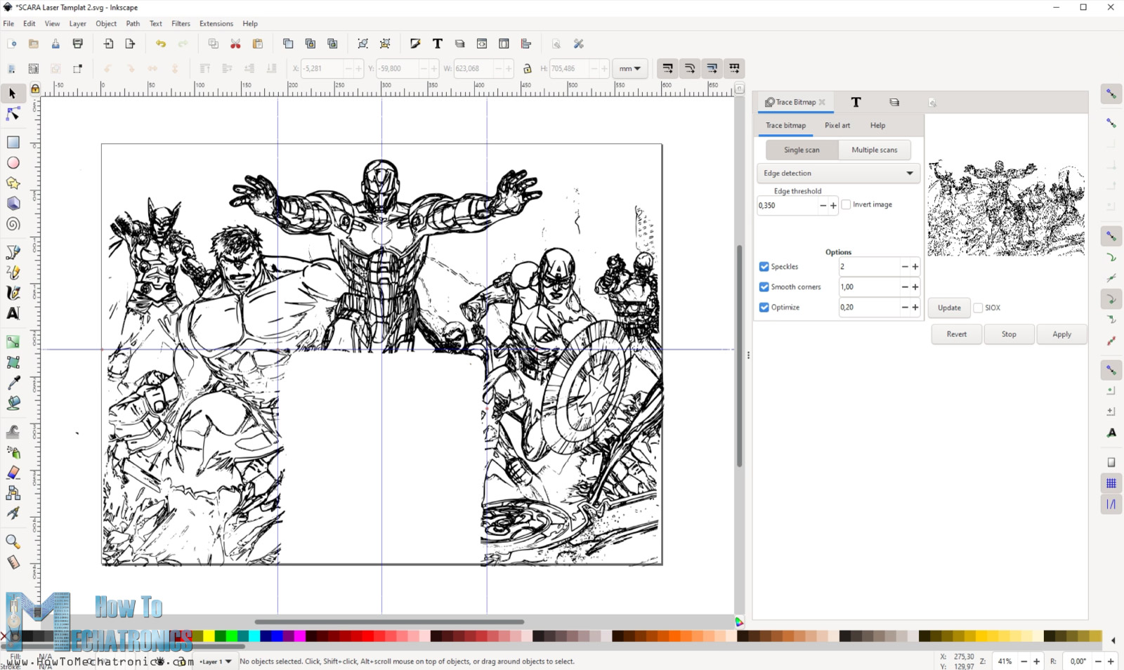
Then I generated the G-code let the machine do its job. It took 4 hours to laser engrave this drawing.
Once it finished, I wanted to fill the empty area where the robot was. For that purpose, I reposition the robot and the work piece, as well as changed the Marlin parameters so that the new work area of the robot is this empty space on the work piece.

Overall, this method requires some work for setting it up, but still it works great. I really like how this engraving turned out.
Wrap up
To wrap up, although there were some problems with the firmware, I managed to find workarounds to them get this SCARA robot working as laser engraver. If we take a closer look to the engraving, we can see that it’s far from perfect.
The robot is not that rigid and has some backlash, and therefore we cannot get precise and smooth movements. However, the things we learned in this tutorial can be implemented in any SCARA robot so you can definitely get better results.
I hope you enjoyed this tutorial and learned something new. Feel free to ask any question in the comments section below and check my Arduino Projects Collection.
Hello I just wanted to say I really admire your work and I have a suggestion for a project, Could you turn this robot into a 3-D printer, by replacing the laser and changing the code. And then make the pieces from wood instead so it would be really cool for those who can’t afford their own 3-D printer. Again I really love your work and I someday wish to have a website as great as yours.
Thank you! Sure, you use this robot as 3D printer as well. I plan to make that project soon, so stay tuned.
Thank you! Sure, you use this robot as 3D printer as well. I plan to make that project soon, so stay tuned.
It’s wonderful that your manipulator can realize the function conversion by replacing the end effector, but the rocker arm structure is not very stable. It would be good if it could be replaced with a frame.