In this tutorial we will learn how to make an Arduino based RC receiver. Since building my DIY Arduino RC transmitter in one of my previous videos, I got a lot of requests from you guys, to make a dedicated receiver for it, so here it is.
You can watch the following video or read the written tutorial below.
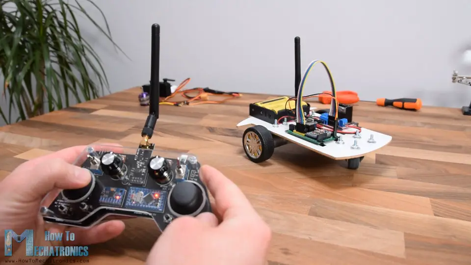
Now these two devices can easily communicate and we can use them for controlling many things wirelessly. I will explain how everything works through few examples. In the first example we will use this Arduino RC receiver to control a simple car consisting of two DC motors. In the second example I will show you how to control brushless motors and servos, which are common components found in many commercial RC planes, boats, cars and so on. If we know how to control them, we can easily modify and control many RC models with our own custom-build Arduino transmitter.
As a third example I will show you how I modified and used this Arduino based RC system to control a commercial RC car.
Arduino RC Receiver Circuit Diagram
To begin with, let’s take a look at the circuit diagram of this system. The radio communication is based on the NRF24L01 transceiver modules.
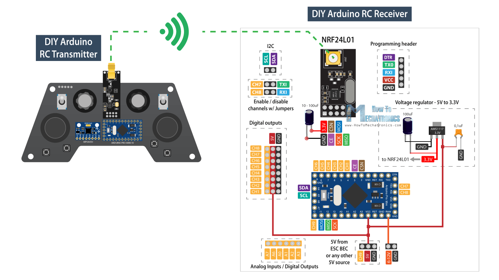
The transmitter constantly sends data from its controllers, the joysticks, the buttons, the potentiometers and the toggle switches, and we receive this data with the receiver. For more details how this Arduino transmitter works you can check my other detailed tutorial for it.
We can also note here that this RC receiver doesn’t necessarily work with only this particular Transmitter that I built. It can work with any other similar setup consisting of an Arduino board and a NRF24L01 module.
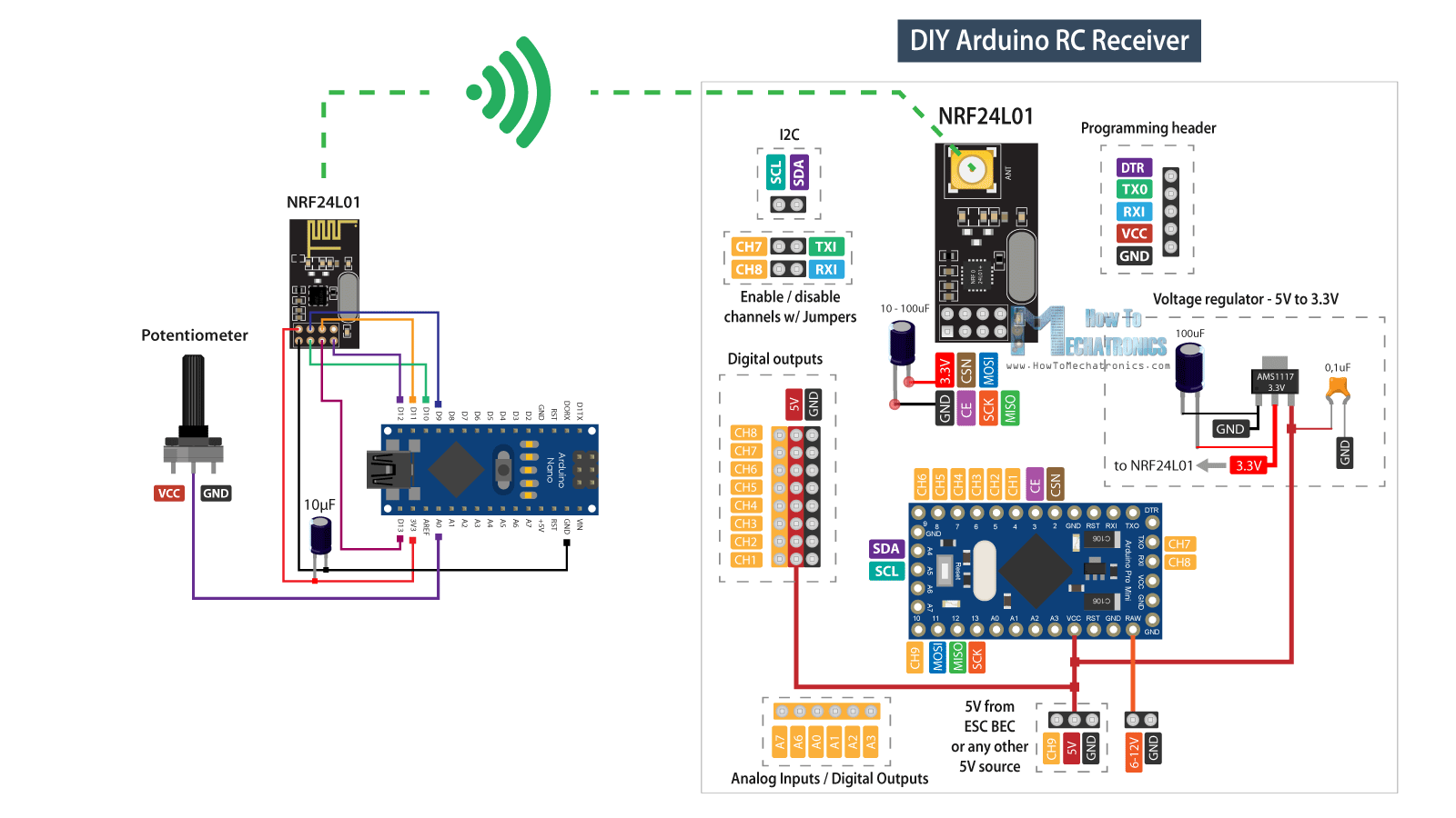
Nevertheless, the brain of this RC receiver is an Arduino Pro Mini board. For powering, we can either use the VCC pin to which we can connect 5V, or the RAW pin to which we can connect from 6 to 12V. Note that there are two versions of the Arduino Pro Mini, like the one I use here that operates at 5V and the other operates at 3.3V. On the other hand, the NRF24L01 module operates at 3.3V, so therefore we need a voltage regulator. This time I’m using the AMS1117 voltage regulator, which outputs 3.3V from inputs which can range from 5V to 12V.
You can get the components needed for this Arduino RC Receiver from the links below:
- NRF24L01 Transceiver Module…….……… Amazon / Banggood / AliExpress
- NRF24L01 + PA + LNA …………………..……. Amazon / Banggood / AliExpress
- AMS1117 3.3V Voltage regulator ……….. Amazon / Banggood / AliExpress
- Pin Headers Male + Female ……………….. Amazon / Banggood / AliExpress
- Arduino Pro Mini………………..……..……….. Amazon / Banggood / AliExpress
- Arduino Pro Mini like the one I used…… Ebay
Disclosure: These are affiliate links. As an Amazon Associate I earn from qualifying purchases.
For communication with the Arduino, the NRF24L01 module uses the SPI protocol, plus two additional digital pins. That means we are left with 9 digital pins which can be used as output channels, two of which are the RX and the TX pins. It’s worth noting, that these pins must be disconnected from anything while we are uploading a sketch to the Arduino board, so therefore I made it possible to be connected or disconnected through separate pin headers. Actually, we can also use the analog inputs as digital outputs, so although this Arduino board is quite small, we got plenty of outputs or channels available.
PCB Design
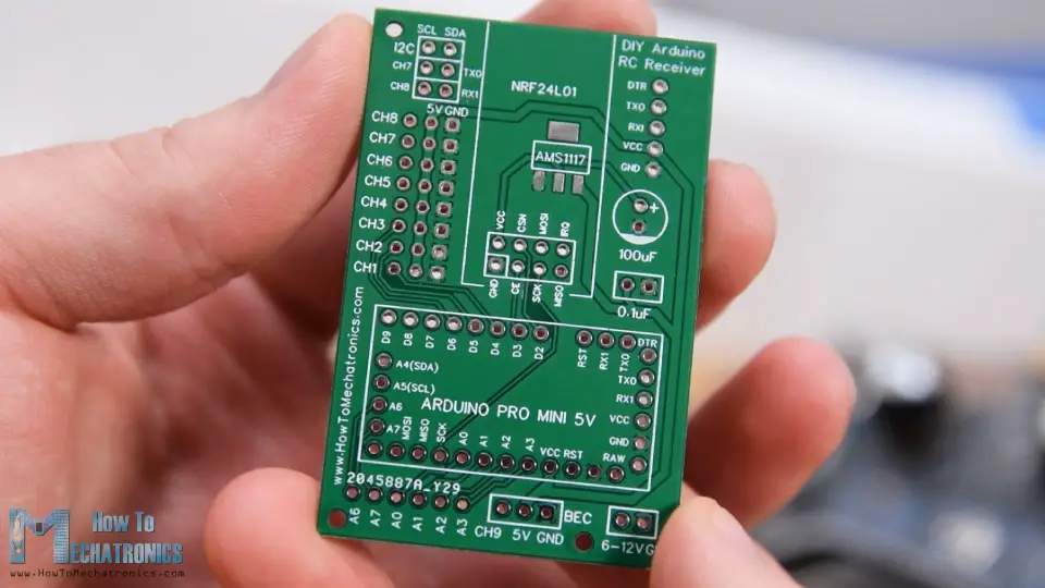
Nevertheless, in order to keep this circuit compact, I made a custom PCB using the EasyEDA free online circuit design software. Here, I arranged the 8 channels right next to a 5V and a Ground rail, and so we can directly connect servos and ECSs to them. The channel number 9 is located at a separate position, near the VCC pin of the Arduino, so we can use for example, an ESC for powering the Arduino with its Battery Eliminator Circuit feature which provides 5V. Of course, we could use any other channels for that purpose, as the VCC pin is connected to those 5V rail as well.
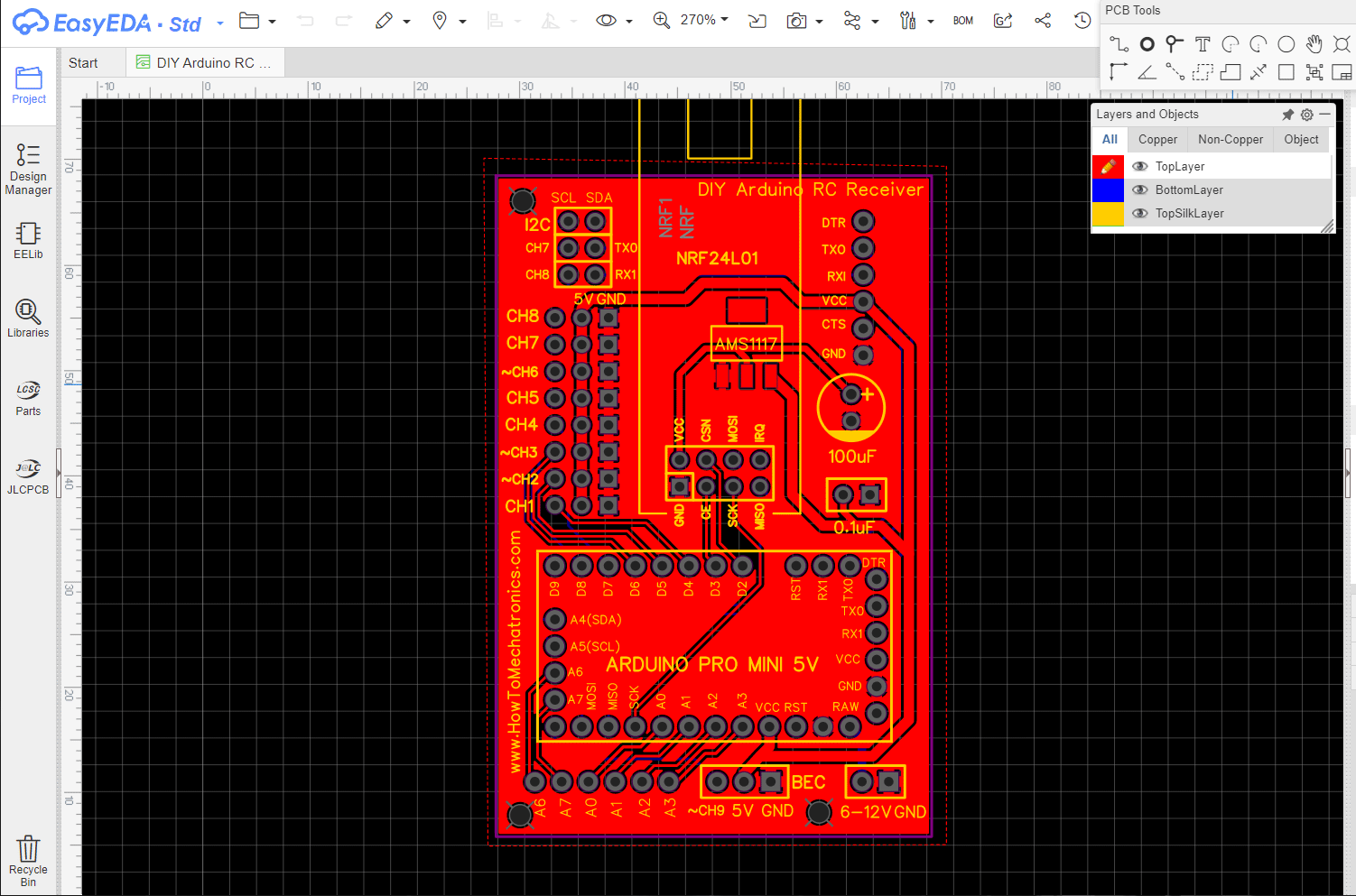
As for the channels number 7 and 8, we can see here how there are interrupted with these pin headers. If we want to use them, we just have to connect the two pins together. The programming header is located at the top right corner and the 100uF capacitor serves for both the voltage regulator and the NRF24L01 module. On the bottom left corner of the PCB, I placed the analog pins.
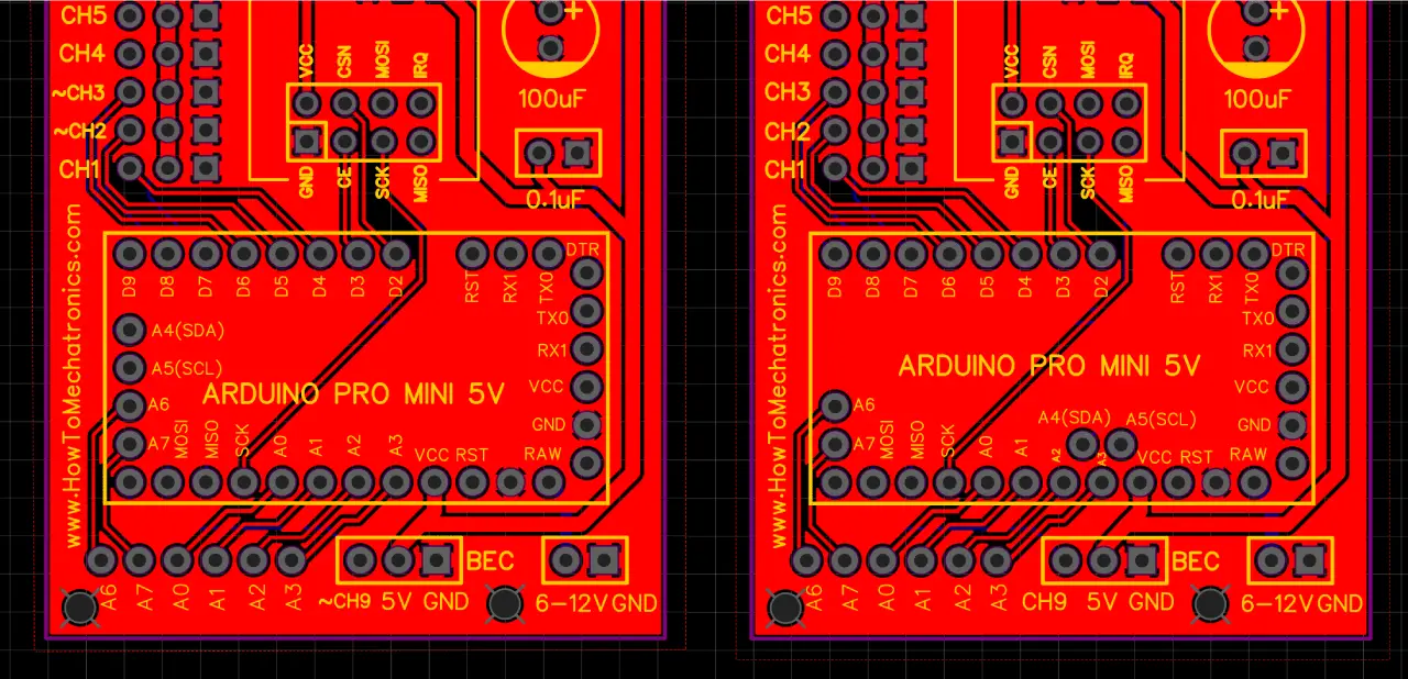
Here we can note one more thing, and that’s that some Arduino Pro Mini boards might have different pins arrangement, so therefore I included one more version of the PCB so you can choose the one that match with your Arduino Pro Mini board.
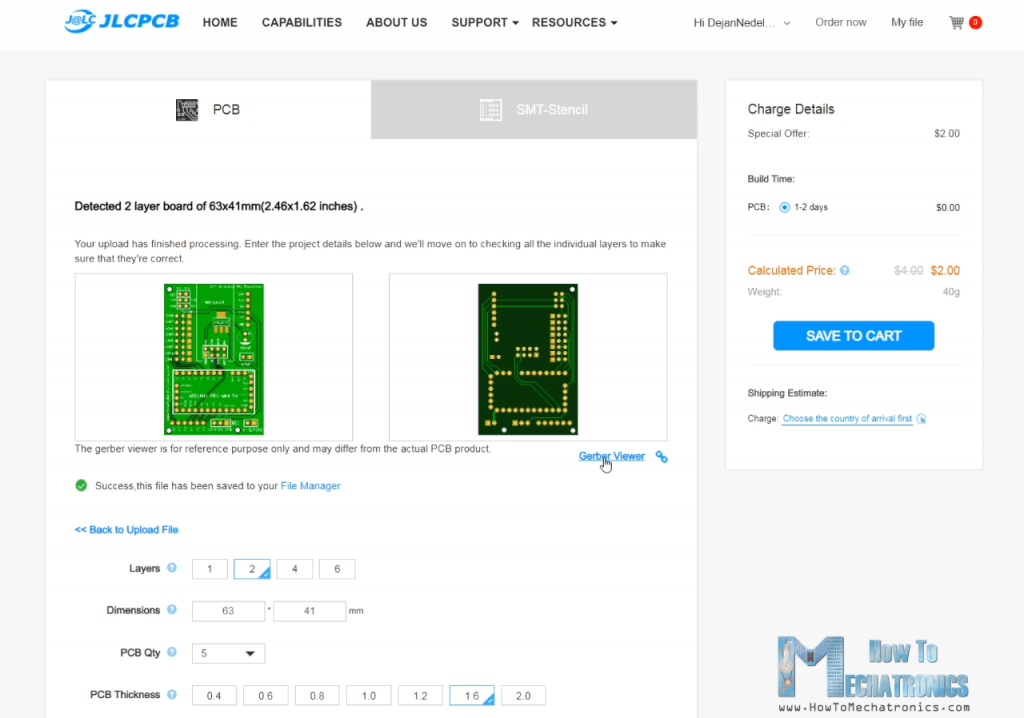
Here’s a link to the project files of this PCB. So once I finished the design, I generated the Gerber file needed for manufacturing the PCB.
Gerber files:
Then I ordered the PCB from JLCPCB which are also the sponsor of this video.

Here we can simply drag and drop the Gerber file and once uploaded, we can review our PCB in the Gerber viewer. If everything is all right then we can go on and select the properties that we want for our PCB. And that’s it, now we can simply order our PCB at a reasonable price. Note that if it’s your first order from JLCPCB, you can get up to 5 PCBs for only $2.
PCB Assembly
After several days the PCBs have arrived. The quality of the PCBs is great and everything is exactly the same as in the design.
Now we can move on and assemble the PCB. First, we need to solder the pin headers of the Arduino board. A convenient way to do that is to use a breadboard to stick the pin headers in it and so the board will stay firmly in place while soldering. As I said earlier, depending on your board, the pins might vary a bit, so keep that in mind when soldering them.
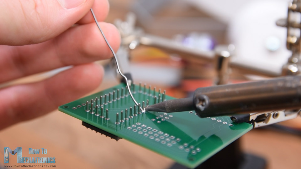
Also, there are some Ground pins that we need to leave free as there are some traces running on the PCB under them. Once I soldered the Arduino board, I cut the excess length off the pins.
Next, I placed all other pin headers in place. We need both male and female pin headers, or it’s actually up to you what pin headers you will choose to use. However, it’s good idea to use male pin headers for the digital channels as the servo motors and the ESC connections are female, so we can easily connect them.
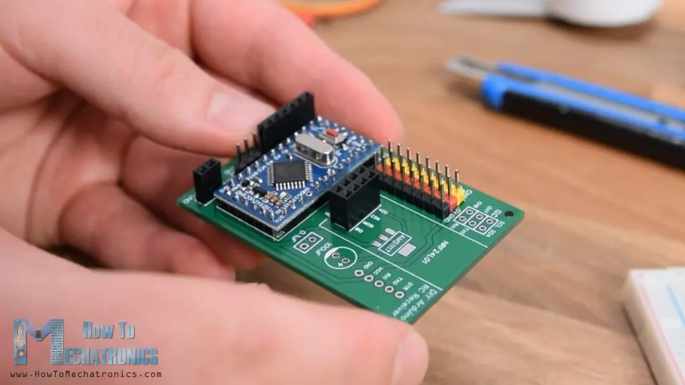
The voltage regulator is a surface mount component so I used some Blue-Tack adhesive to hold it in place while soldering. Lastly, once we solder the two capacitors in place, we can attach the NRF24L01 module to the appropriate pin headers.
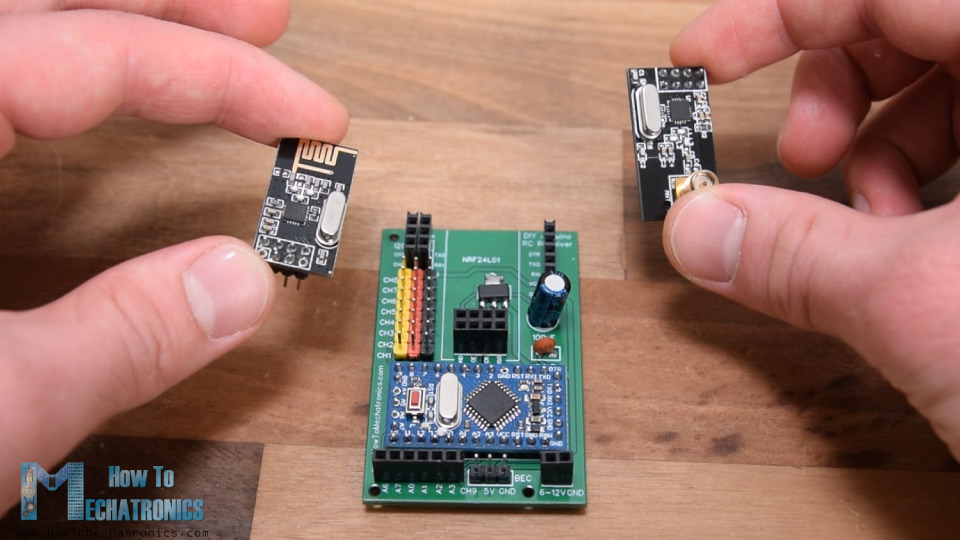
Depending on the application, or the range that we need, we can use either the normal module with the on-board antenna, or the one to which we can attach a bigger antenna and can achieve wireless communication of up to 700 meters in open space. So that’s it, our Arduino RC Receiver is now ready and we can use it for anything we want.
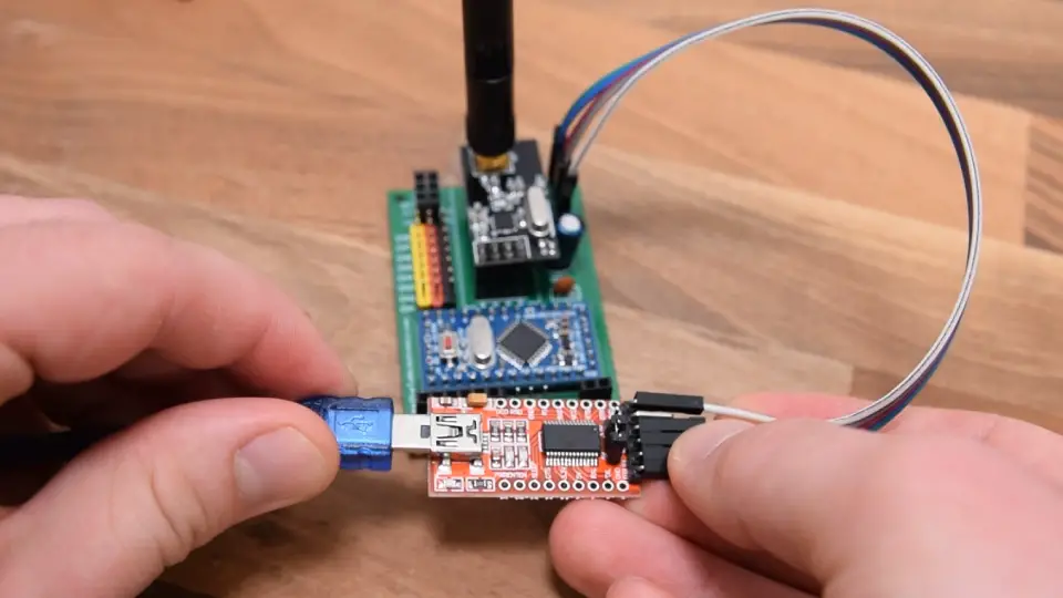
For programming the receiver, or connecting the Arduino Pro Mini to the computer, we can use an USB to serial UART interface which can be connected to the programing header.
In the Arduino IDE tools menu we need to select the Arduino Pro or Pro Mini board, select the proper version of the processor, select the port and select the programming method to “USBasp”.
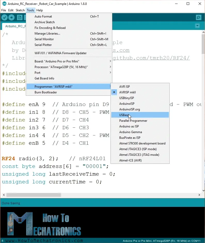
And so now we are able to upload codes to the Arduino.
Example 1 – Arduino RC Car
Ok, now we can move on and take a look at the first example.
It’s a simple car consisting of two 12V DC motors and in some of my previous videos I have already showed you how it works and how to build it.
See also: L298N Motor Driver – Arduino Interface, How It Works, Codes, Schematics
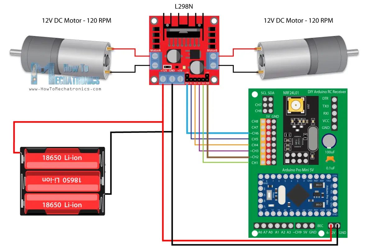
This time we will use our new Arduino RC receiver for controlling it. For driving the DC motors, we are using the L298N motor driver and for powering, we are using 3 Li-ion batteries which provide around 12V.
You can get the components needed for this example from the links below:
- L298N Driver ……………………………….. Amazon / Banggood / AliExpress
- 12V High Torque DC Motor ………….. Amazon / Banggood / AliExpress
- DC Motor w/ Plastic Tire Wheel ……. Amazon / Banggood / AliExpress
- Breadboard and Jump Wires ………… Amazon / Banggood / AliExpress
Disclosure: These are affiliate links. As an Amazon Associate I earn from qualifying purchases.
So, the connections are really simple, the 12V coming from the batteries go the 12V pin on our receiver, and the six control pins of the driver go to the 6 channels. We need to note here that in order to be able to control the speed of the motors we need to provide PWM signal to the Enable A and Enable B pins of the driver. In our receiver the channels number 2, 3, 6 and 9 can output PWM signals, so there I connected the Enable pins of the driver to the channels number 2 and 6 in this case.
Let’s take a look at the Arduino code now.
/*
Arduino RC Receiver - Car Example
by Dejan, www.HowToMechatronics.com
Library: TMRh20/RF24, https://github.com/tmrh20/RF24/
*/
#include <SPI.h>
#include <nRF24L01.h>
#include <RF24.h>
#define enA 9 // Arduino pin D9 - CH6 on PCB board - PWM output
#define in1 8 // D8 - CH5
#define in2 7 // D7 - CH4
#define in3 6 // D6 - CH3
#define in4 4 // D4 - CH1
#define enB 5 // D5 - CH2 - PWM output
RF24 radio(3, 2); // nRF24L01 (CE, CSN)
const byte address[6] = "00001";
unsigned long lastReceiveTime = 0;
unsigned long currentTime = 0;
// Max size of this struct is 32 bytes
struct Data_Package {
byte j1PotX;
byte j1PotY;
byte j1Button;
byte j2PotX;
byte j2PotY;
byte j2Button;
byte pot1;
byte pot2;
byte tSwitch1;
byte tSwitch2;
byte button1;
byte button2;
byte button3;
byte button4;
};
Data_Package data; //Create a variable with the above structure
int steering, throttle;
int motorSpeedA = 0;
int motorSpeedB = 0;
void setup() {
pinMode(enA, OUTPUT);
pinMode(enB, OUTPUT);
pinMode(in1, OUTPUT);
pinMode(in2, OUTPUT);
pinMode(in3, OUTPUT);
pinMode(in4, OUTPUT);
//Serial.begin(9600);
radio.begin();
radio.openReadingPipe(0, address);
radio.setAutoAck(false);
radio.setDataRate(RF24_250KBPS);
radio.setPALevel(RF24_PA_LOW);
radio.startListening(); // Set the module as receiver
resetData();
}
void loop() {
// Check whether we keep receving data, or we have a connection between the two modules
currentTime = millis();
if ( currentTime - lastReceiveTime > 1000 ) { // If current time is more then 1 second since we have recived the last data, that means we have lost connection
resetData(); // If connection is lost, reset the data. It prevents unwanted behavior, for example if a drone jas a throttle up, if we lose connection it can keep flying away if we dont reset the function
}
// Check whether there is data to be received
if (radio.available()) {
radio.read(&data, sizeof(Data_Package)); // Read the whole data and store it into the 'data' structure
lastReceiveTime = millis(); // At this moment we have received the data
}
// Parse the data from the Joystic 1 to the throttle and steering variables
throttle = data.j1PotY;
steering = data.j1PotX;
// Throttle used for forward and backward control
// Joystick values: 0 to 255; down = 0; middle = 127; up = 255
if (throttle < 110) {
// Set Motor A backward
digitalWrite(in1, HIGH);
digitalWrite(in2, LOW);
// Set Motor B backward
digitalWrite(in3, HIGH);
digitalWrite(in4, LOW);
// Convert the declining throttle readings for going backward from 110 to 0 into 0 to 255 value for the PWM signal for increasing the motor speed
motorSpeedA = map(throttle, 110, 0, 0, 255);
motorSpeedB = map(throttle, 110, 0, 0, 255);
}
else if (throttle > 140) {
// Set Motor A forward
digitalWrite(in1, LOW);
digitalWrite(in2, HIGH);
// Set Motor B forward
digitalWrite(in3, LOW);
digitalWrite(in4, HIGH);
// Convert the increasing throttle readings for going forward from 140 to 255 into 0 to 255 value for the PWM signal for increasing the motor speed
motorSpeedA = map(throttle, 140, 255, 0, 255);
motorSpeedB = map(throttle, 140, 255, 0, 255);
}
// If joystick stays in middle the motors are not moving
else {
motorSpeedA = 0;
motorSpeedB = 0;
}
// Steering used for left and right control
if (steering < 110) {
// Convert the declining steering readings from 140 to 255 into increasing 0 to 255 value
int xMapped = map(steering, 110, 0, 0, 255);
// Move to left - decrease left motor speed, increase right motor speed
motorSpeedA = motorSpeedA - xMapped;
motorSpeedB = motorSpeedB + xMapped;
// Confine the range from 0 to 255
if (motorSpeedA < 0) {
motorSpeedA = 0;
}
if (motorSpeedB > 255) {
motorSpeedB = 255;
}
}
if (steering > 140) {
// Convert the increasing steering readings from 110 to 0 into 0 to 255 value
int xMapped = map(steering, 140, 255, 0, 255);
// Move right - decrease right motor speed, increase left motor speed
motorSpeedA = motorSpeedA + xMapped;
motorSpeedB = motorSpeedB - xMapped;
// Confine the range from 0 to 255
if (motorSpeedA > 255) {
motorSpeedA = 255;
}
if (motorSpeedB < 0) {
motorSpeedB = 0;
}
}
// Prevent buzzing at low speeds (Adjust according to your motors. My motors couldn't start moving if PWM value was below value of 70)
if (motorSpeedA < 70) {
motorSpeedA = 0;
}
if (motorSpeedB < 70) {
motorSpeedB = 0;
}
analogWrite(enA, motorSpeedA); // Send PWM signal to motor A
analogWrite(enB, motorSpeedB); // Send PWM signal to motor B
}
void resetData() {
// Reset the values when there is no radio connection - Set initial default values
data.j1PotX = 127;
data.j1PotY = 127;
data.j2PotX = 127;
data.j2PotY = 127;
data.j1Button = 1;
data.j2Button = 1;
data.pot1 = 1;
data.pot2 = 1;
data.tSwitch1 = 1;
data.tSwitch2 = 1;
data.button1 = 1;
data.button2 = 1;
data.button3 = 1;
data.button4 = 1;
}Code language: Arduino (arduino)Description: So first we need to include the SPI and the RF24 library, define some pins, the radio object, and the data structure where we will store the incoming data from the transmitter. In the setup section we need to define the pin outputs and begin the radio communication. For more details how this works and what each these lines do, you can check my detailed NRF24L01 tutorial.
In the loop section, we constantly check whether we are receiving data and if we do, we read that incoming data. If we take a quick look at the transmitter code, we can see what kind of data it sends to the receiver. It reads the data from all its controllers, the joysticks, the potentiometers and the buttons, and it sends that data as a single package to the receiver.
So, once we read that data, we can do whatever we want with it. In this case, we will use the Joystick 1 Y-axis value for controlling the throttle and the X-axis value for controlling the steering. I put this data into separate throttle and steering variables. The values we are getting from the joysticks are from 0 to 255. So, if we move the joystick down, we will set the driver control pins appropriately so the car moves backwards, and use the throttle value for controlling the speed of movement. The same principle applies for driving forward, left and right. Again, I already have a detailed tutorial on how this car works so you can check that out for better understanding. At the bottom of the code we can note the resetData() custom function, which reset all values to their initial default values so in case the radio communication is lost, the car will spot moving.
Example 2 – Arduino RC Receiver Servos and Brushless Motors Control
All right, now we can move on with the second example, controlling servos and brushless motors using this Arduino RC receiver.
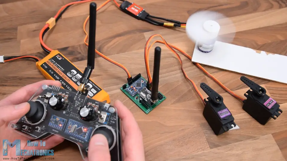
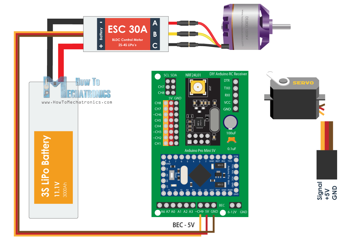
For controlling brushless motors, we need an ESC, or Electronic Speed Controller. The Arduino communicates to the ESC with just a single pin. For controlling the ESC, the Arduino sends a specific PWM signal to the ESC and with it the ESC controls the motor speed. The ESC with that same connection provides 5V through its Battery Eliminator Circuit feature, so we can power our receiver with it as well.
See also: Arduino Brushless Motor Control Tutorial | ESC | BLDC
As for the servo motors, they have the same type of connections as the ESC and we can simply attach them to any of the channels that are available.
You can get the components needed for this example from the links below:
- Brushless Motor ……………………….. Amazon / Banggood / AliExpress
- ESC 30A ……………………………………… Amazon / Banggood / AliExpress
- Li-Po battery ……………………..…… Amazon / Banggood / AliExpress
- MG996R Servo Motor ……………… Amazon / Banggood / AliExpress
Disclosure: These are affiliate links. As an Amazon Associate I earn from qualifying purchases.
The input signals for controlling both servos and brushless motors using ESCs are almost the same. They use specific 50Hz PWM signal which can be easily generated using the Arduino Servo library.
Note: When using MG996R servos with this setup, they might cause a problem in the circuit and burn the Arduino Pro Mini. The might draw a higher current and which could cause voltage spikes at the 5V rail. The Arduino Pro Mini should handle up to 5.5v at the 5V pin, but when those spikes occur that might burn the Arduino. I had this problem when testing the circuit, and someone in the comments section also reported the same. A solution to this might be place a bigger decoupling capacitors at the servos but I’m not quite sure and I haven’t tested it. So please be aware of this problem.
On the other hand, in the example I used two other MG996R servos which didn’t burn the Arduino, I guess because they weren’t causing such high spikes. Also I used this example with 4 smaller S90 servos and it didn’t have any problem.
See also: How Servo Motor Works & How To Control Servos using Arduino
/*
  DIY RC Receiver - Servos and Brushless motors control
  by Dejan, www.HowToMechatronics.com
  Library: TMRh20/RF24, https://github.com/tmrh20/RF24/
*/
#include <SPI.h>
#include <nRF24L01.h>
#include <RF24.h>
#include <Servo.h>

RF24 radio(3, 2);   // nRF24L01 (CE, CSN)
const byte address[6] = "00001";
unsigned long lastReceiveTime = 0;
unsigned long currentTime = 0;
Servo esc;  // create servo object to control the ESC
Servo servo1;
Servo servo2;
int escValue, servo1Value, servo2Value;
// Max size of this struct is 32 bytes - NRF24L01 buffer limit
struct Data_Package {
  byte j1PotX;
  byte j1PotY;
  byte j1Button;
  byte j2PotX;
  byte j2PotY;
  byte j2Button;
  byte pot1;
  byte pot2;
  byte tSwitch1;
  byte tSwitch2;
  byte button1;
  byte button2;
  byte button3;
  byte button4;
};
Data_Package data; //Create a variable with the above structure
void setup() {
  Serial.begin(9600);
  radio.begin();
  radio.openReadingPipe(0, address);
  radio.setAutoAck(false);
  radio.setDataRate(RF24_250KBPS);
  radio.setPALevel(RF24_PA_LOW);
  radio.startListening(); //  Set the module as receiver
  resetData();
  esc.attach(10);   // Arduino digital pin D10 - CH9 on PCB board
  servo1.attach(4); // D4 - CH1
  servo2.attach(5); // D5 - CH2
}
void loop() {

  // Check whether we keep receving data, or we have a connection between the two modules
  currentTime = millis();
  if ( currentTime - lastReceiveTime > 1000 ) { // If current time is more then 1 second since we have recived the last data, that means we have lost connection
    resetData(); // If connection is lost, reset the data. It prevents unwanted behavior, for example if a drone jas a throttle up, if we lose connection it can keep flying away if we dont reset the function
  }

  // Check whether there is data to be received
  if (radio.available()) {
    radio.read(&data, sizeof(Data_Package)); // Read the whole data and store it into the 'data' structure
    lastReceiveTime = millis(); // At this moment we have received the data
  }

  // Controlling servos
  servo1Value = map(data.j2PotX, 0, 255, 0, 180); // Map the receiving value form 0 to 255 to 0 to 180(degrees), values used for controlling servos
  servo2Value = map(data.j2PotY, 0, 255, 0, 180);
  servo1.write(servo1Value);
  servo2.write(servo2Value);

  // Controlling brushless motor with ESC
  escValue = map(data.j1PotY, 127, 255, 1000, 2000); // Map the receiving value form 127 to 255 to  1000 to 2000, values used for controlling ESCs
  esc.writeMicroseconds(escValue); // Send the PWM control singal to the ESC

}
void resetData() {
  // Reset the values when there is no radio connection - Set initial default values
  data.j1PotX = 127;
  data.j1PotY = 127;
  data.j2PotX = 127;
  data.j2PotY = 127;
  data.j1Button = 1;
  data.j2Button = 1;
  data.pot1 = 1;
  data.pot2 = 1;
  data.tSwitch1 = 1;
  data.tSwitch2 = 1;
  data.button1 = 1;
  data.button2 = 1;
  data.button3 = 1;
  data.button4 = 1;
}Code language: Arduino (arduino)
So, after receiving the data from the transmitter, we convert the values from 0 to 255 to values from 0 to 180 for controlling the servos using the write() function. In similar way, we convert the data for controlling the ESC to values from 1000 to 2000. In this example we control this ESC from the middle point of the Joystick number 1, to the up position, so therefore we convert the values from the middle, 127 to 255 into values from 1000 to 2000. Using the Servo Library writeMicroseconds() function we send the PWM signal to the ESC and so we can control the speed of the brushless motor from minimum to maximum.
See also: Arduino RC Airplane | 100% DIY
So, this is how we can control RC airplanes, cars, boats and so on, as they are usually using this type of motors, servos and brushless motors.
Example 3 – RC Car Model Control
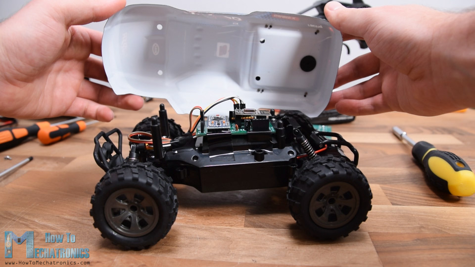
The RC car came with its own controller which can control the front wheels to move left and right, as well as move the car forward and backward.
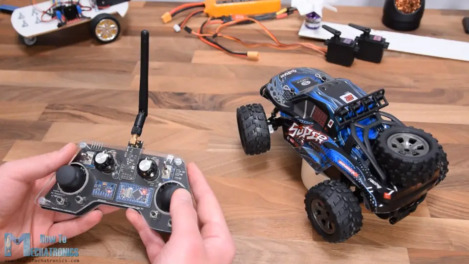
However, as it’s a cheap RC car, the controls are digital, or either on or off, to maximum position left and right and maximum speed. Regardless of that, I disassembled the car to see what’s inside and how I can implement the Arduino RC receiver for controlling it.
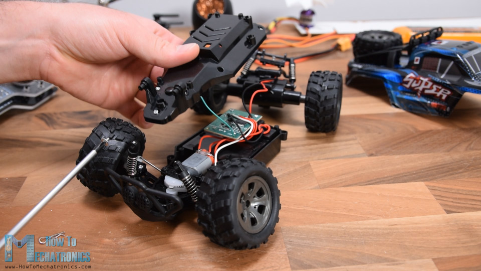
Once I uncovered the electronic components, I noticed that the two motors are actually simple DC motors that operate at 5V. Even the front motor which controls the limited movements for the steering is a simple continuous rotation DC motor.
So, apparently, we already know how to control DC motors, so replacing this circuit board with our DIY Arduino receiver will be quite easy. In addition to our receiver we just need a motor driver capable of driving two motors at the same time. There are plenty of options for that purpose, even the one we used in the first example, the L298N driver.
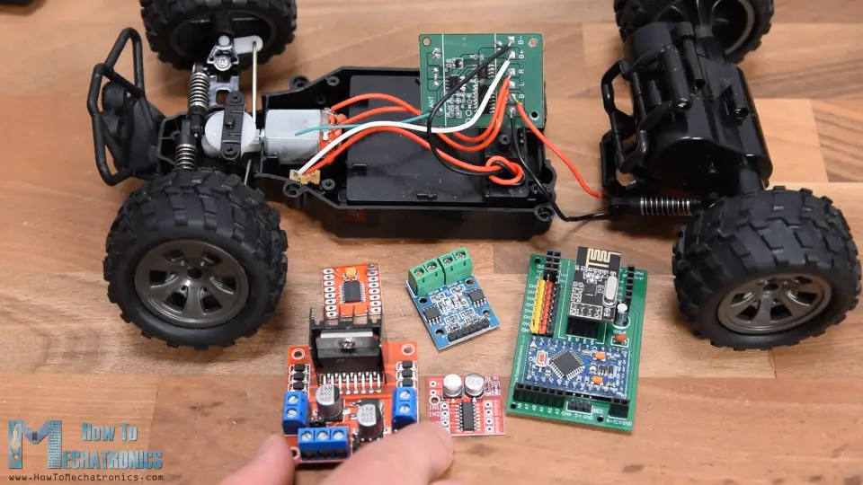
However, that one is too big for this application, so I chose the MX1508 motor driver. This is a simple dual DC motor driver which features H-bridge and PWM control. It has 4 control inputs pins, 4 pins for the motors, and 2 pins for powering.
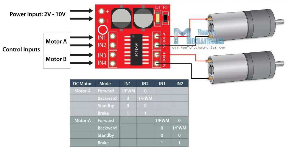
I desoldered the motors connections from the RC car circuit board and soldered them to the driver. On the back side I soldered the power pins and what’s left now is to connect this driver with the receiver. The power for this RC car comes from 4.8V Ni-Cd battery located at the bottom of the car.
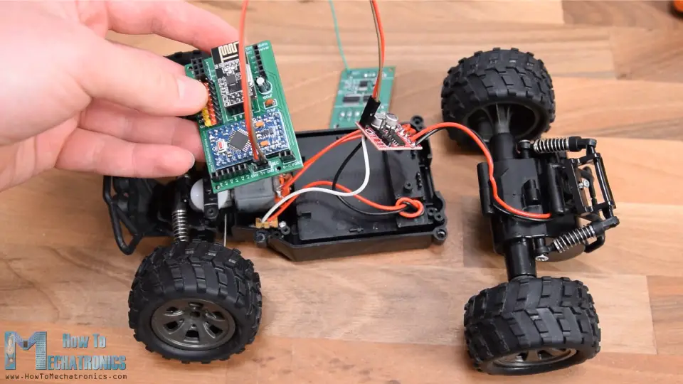
So, using jump wires I connected these pins to the VCC pin of the Arduino, and also connected the 4 control input pins of the driver to 4 digital channels. As I said, this driver supports PWM control, so for the motor B, or the rear motor, I used the PWM channels number 2 and 3.

You can get the components needed for this example from the links below:
- MGRC RC Car ………………………………… Amazon / Banggood / AliExpress
- MX1508 DC Motor Driver ……………… Amazon / Banggood / AliExpress
- Breadboard and Jump Wires ………… Amazon / Banggood / AliExpress
Disclosure: These are affiliate links. As an Amazon Associate I earn from qualifying purchases.
The code for this RC car is very similar to the first example.
/*
   Arduino RC Receiver - RC Model control
   by Dejan , www.HowToMechatronics.com
   Library: TMRh20/RF24, https://github.com/tmrh20/RF24/
*/
#include <SPI.h>
#include <nRF24L01.h>
#include <RF24.h>

#define in3 5  // D5 - CH2 - PWM output
#define in4 6  // D6 - CH3 - PWM output
#define in1 7  // D7 - CH4
#define in2 8  // D8 - CH5


RF24 radio(3, 2);   // nRF24L01 (CE, CSN)
const byte address[6] = "00001";
unsigned long lastReceiveTime = 0;
unsigned long currentTime = 0;

// Max size of this struct is 32 bytes
struct Data_Package {
  byte j1PotX;
  byte j1PotY;
  byte j1Button;
  byte j2PotX;
  byte j2PotY;
  byte j2Button;
  byte pot1;
  byte pot2;
  byte tSwitch1;
  byte tSwitch2;
  byte button1;
  byte button2;
  byte button3;
  byte button4;
};

Data_Package data; //Create a variable with the above structure

int  steering, throttle;
int motorSpeedA = 0;
int motorSpeedB = 0;

void setup() {
  pinMode(in1, OUTPUT);
  pinMode(in2, OUTPUT);
  pinMode(in3, OUTPUT);
  pinMode(in4, OUTPUT);
  Serial.begin(9600);
  radio.begin();
  radio.openReadingPipe(0, address);
  radio.setAutoAck(false);
  radio.setDataRate(RF24_250KBPS);
  radio.setPALevel(RF24_PA_LOW);
  radio.startListening(); //  Set the module as receiver
  resetData();
}
void loop() {
  // Check whether we keep receving data, or we have a connection between the two modules
  currentTime = millis();
  if ( currentTime - lastReceiveTime > 1000 ) { // If current time is more then 1 second since we have recived the last data, that means we have lost connection
    resetData(); // If connection is lost, reset the data. It prevents unwanted behavior, for example if a drone jas a throttle up, if we lose connection it can keep flying away if we dont reset the function
  }
  // Check whether there is data to be received
  if (radio.available()) {
    radio.read(&data, sizeof(Data_Package)); // Read the whole data and store it into the 'data' structure
    lastReceiveTime = millis(); // At this moment we have received the data
  }
  // Parse the data from the Joystic 1 to the steering and throttle variables
  steering = data.j2PotX;
  throttle = data.j1PotY;


// Throttle used for forward and backward control
  if (throttle < 110) {
    // Convert the declining throttle readings for going backward from 110 to 0 into 0 to 255 value for the PWM signal for increasing the motor speed
    motorSpeedB = map(throttle, 110, 0, 0, 255);
    // Set Motor B backward
    analogWrite(in3, motorSpeedB);
    digitalWrite(in4, LOW);
  }
  else if (throttle > 140) {
    // Convert the increasing throttle readings for going forward from 140 to 255 into 0 to 255 value for the PWM signal for increasing the motor speed
    motorSpeedB = map(throttle, 140, 255, 0, 255);
    // Set Motor B forward
    digitalWrite(in3, LOW);
    analogWrite(in4, motorSpeedB);
  }
  // If joystick stays in middle the motors are not moving
  else {
    digitalWrite(in3, HIGH);
    digitalWrite(in4, HIGH);
  }

// steering used for left and right control
  if (steering < 110) {
    digitalWrite(in1, HIGH);
    digitalWrite(in2, LOW);
  }
  if (steering > 140) {
    digitalWrite(in1, LOW);
    digitalWrite(in2, HIGH);
  }
  // If joystick stays in middle the motors are not moving
  else {
    digitalWrite(in1, HIGH);
    digitalWrite(in2, HIGH);
  }
}
void resetData() {
  // Reset the values when there is no radio connection - Set initial default values
  data.j1PotX = 127;
  data.j1PotY = 127;
  data.j2PotX = 127;
  data.j2PotY = 127;
  data.j1Button = 1;
  data.j2Button = 1;
  data.pot1 = 1;
  data.pot2 = 1;
  data.tSwitch1 = 1;
  data.tSwitch2 = 1;
  data.button1 = 1;
  data.button2 = 1;
  data.button3 = 1;
  data.button4 = 1;
}Code language: Arduino (arduino)
We use the data coming from the joysticks to control the throttle and the steering of the RC car. For moving backward we use the analogWrite() function to send PWM signal to the driver at the Input3 pin, while we hold the input4 pin LOW. For moving forward, we do that the opposite way. If the joystick stays in the middle, we give command to the driver to brake or stop the motors. The same principle is used for the steering motor, though here we don’t have to use the analogWrite() function as we don’t need to control the speed of this motor.
After uploading this sketch to the Arduino, I had to reassemble the RC car. I placed the small driver in the inside housing and secured the rest of the parts with the screws. I reconnected the receiver with the driver, and placed it under the outer housing of the car which had enough place to fit in the receiver.
So, not only we modified this RC car to be controlled with our DIY RC transmitter, but also improved it by adding PWM control so now we can also control the speed of car. In case the RC model you want to modify has servos and brushless motors instead of DC motors, you can follow the method explained in the second example.
I hope you enjoyed this tutorial and learned something new . Feel free to ask any question in the comments section below and don’t forget to check my collection of Arduino Projects.
Hi Dejna
I really like your website and your work. I would have a question: Can this servo be used to operate 2 servos and 6 dc motors (at the same speed) with this rc receiver?
Thank you, Gábor.
Hey, thanks! Well it has 9 channels so yes, it can control 2 servos and 6 DC motors at the same time.
Hi, Dejan. Thank you very much for the great project. I found the Arduino Pro mini can’t provide enough power for MG996R. Is it possible to add a mini dc converter to the pcb? MP1584EN or mini360 is a great one for instance. Thank you again.
That’s true, the Arduino Pro mini can’t provide enough power for a MG996R servo, so adding a DC converter to the PCB is good idea.
using the 2nd example’s codes can we control brushed escs to drive the maximum no. of motors
First of all: Dejan, thank you very much for the great project. I also build up a transmitter an s receiver and it works quite good (I still have problems with the MPU6050).
Hi Mahargha,
of course you can control brushed escs. The receiver simply generates the signals to control the speed of an esc or servo. But – in case you use more than one esc with a BEC circuit – please disconnect the +5V wires of the other escs to ensure to use a single 5V voltage supply.
I wrote a version using all six potentiometers generating six PWM-signals. Nevertheless, I added a delay of 20ms in the code of the transmitter to get a good result – like an old rc control device sending the data every e.g. 20ms. Without this delay, it doesn’t work. I guess, the servo library has some problems to handle a huge amount of set-points.
I also combined the digital channels (8 switches) using a single “byte” instead of 8 bytes to reduce the size of data to be transmitted and received .
Best regards from Kassel/Germany,
Lothar
Sir can we use in this project l298 as a motor controller
Yes, you could use the L298 motor controller in combination with this RC receiver.
Hey Dejan, is it compulsory to use 0.1 uf capacitor or any other value is fine .
You can use anything similar or close to it.
Hi,i have a
question, also connect other servos to the reciver or only the SG90?
If I use other servos the Arduino pro mini has problems ….
because of the load/ amp ?……
when i that servo MG995 with the reciver connect has the arduino mini pro malfunction
he function then not more…..
Can you help me?
greetings
Wolfgang Rupp
Hey, I’m sorry to hear that. But the same happened to me. I though it was a problem with my particular MG996R motors that I used. They malfunction my Arduino too.
I tried other two MG996R servos and it worked. In the example with the plane I also tried 4 SG90 and it works.
Nevertheless I guess the problem is with the current the MG996R draw and they somehow cause a voltage spike higher that 5.5V, and that burns the Arduino Pro Mini.
Not quite sure, but maybe if you place bigger decoupling capacitors at the servos could help with this problem.
Or you can use separate 5V power supply, instead of the 5V from PCB board.
Sorry about the inconvenience. I will add this note in the article as well so people will be aware of it.
Hi,
is all good, your projects are verry good, the arduino pro mini 5v can only 40mA per exit, i have then the servos separately with electricity provided, and works perfect, also without interference, the MG 995 Servos have, too with me Interference caused.
As soon as I the MG 995 Servo with the Arduino pro mini connect,bother something
if my project is
finished i will send a video,
I’m happy on your next one new projects, and say thank for your Help
Greeting
Wolfgang Rupp
Hi. Great project! I have a question: if we use two identical sets of transmiter-receiver, can we control two models independently at the same time, at the same frequency?
Hey, thanks! Yes, you can change the channel or the name of the “address” variable in the code.
It would be a great event to be able to control your motorized slider camera with pan and tilt with your arduino rc transmitters and arduino rc receiver. Will you be able to do this; it would be your masterpiece. Hello and many compliments for your pages.
Hey, thanks for the comment. It’s true, controlling the motorized camera slider project with the DIY RC transmitter would be really awesome. But I’m afraid, currently I don’t have the time to modify that project. In such a case, the PCB will have to be modified and also the code. It’s not that it’s too hard or it has too much work on it, it’s simple and old project to which I don’t think of going back to it for now. Anyway, if you understand well how the transmitter and the receiver work, you should be able to implement it on your own.
hi dejan.just one quick question.are the PCB single layer or double layer?because i do not know how many layer to choose when ordering from JLPCB.really appreciate your help.
Hey, it’s a 2 layer PCB.
Hi Dejan,
I hope you are fine,………
the transmitter is finished and works perfectly, once took the sketch from the hovercraft, works very well ………..
only for the Arduino pro Mini the new version I had to lay two wires for the pin 4 and 5 on the transmitter board …….
I’m eagerly waiting for your new receiver projects …
Wish you a happy Easter and health
greeting
Wolfgang Rupp from Germany
Hello Dejan,
everything was regulated with the order of the boards from JLCPCB, I had ordered 5 boards, but the ordering process turned into 5 orders, no idea how this could have happened, but now everything is okay, boards are ordered, now it says waiting….
I have a question about the new project, you control the rudder on the RC plane with the potentiometer to fine-tune it, what should the sketch look like?
Many thanks for the help,
Greetings Wolfgang Rupp (Germany)
Hey, that’s great!
Yes, we can fine-tine the RC plane rudder with the potentiometer. I will also include sensitivity control with the second potentiometer. I mean, we can add many features, it’s all about how we can program the receiver.
Stay tuned, the project is coming in a week or two. 🙂
Hello Dejan,
Would it be possible for you to export the gerber files of your Transmitter and Receiver PCBs as a stp.file?
I would greatly appreciate this, so i can print custom cases for both!
Sadly i can not work with just the gerber files and fusion, a trial and error approach using the pictures would be possible, but will waste filament, which right now is better used for face shields!
Again, i would appreciate it very much if you could help with that.
Greetings from Germany
Hey, I don’t have a .stp file from the PCBs and I’m not sure how I can make one. The gerber files is all I have, plus I guess you have already checked the EasyEDA project files, I’m not sure if that would be of any help, but maybe it will. You could use the measuring tool there to get the precise dimensions, but that would be the same as measuring the physical PCB by hand. Let me know if you think of any other idea how to make .stp files for 3D printing.
Hi Dejan,
you guessed wrong and that helped!
I totally missed that EasyEDA project link and its useability for my build, I was able to export it as .dxf-File, which will be usable in Fusion360!
Thanks for the reminder, now i can design a proper Case
Thank you.
Hi,
thanks for the quick help,
I got in touch with JLCPCB this morning and sent the zip file again. I’m still waiting for an answer ……
This is my third order from JLCPCB, the Gerber files from your project RC Sender and the Range Measurer and Digital Spirit Level were also flawless ……..
I will write to you as soon as I hear something
greeting
Wolfgang Rupp
Hi Dejan,
I hope all of you are healthy,
I am overwhelmed by the new project, that is exactly what I was looking for, I almost finished the transmitter, I just had to put the two pins A4 and A5 with short cables to the pins on the board, since I used the Arduino pro mini in the (old version) nowhere to be found.
Your new project
is exactly the right thing, as we should stay at home here in Germany.
This is my second project of yours, the first was Range Measurer and Digital Spirit Level, which I copied, it works great.
Thank you for the new project, stay healthy.
Warm greetings from Germany
Wolfgang Rupp
Hey, thank you, I’m glad to hear it! Have fun building!
Hy,
I ordered the boards yesterday evening with the Gerber file: DIY Arduino RC Receiver PCB v2 – Gerber file
and JLCPCB support,
support wrote me this answer this morning.
Hi sir
Well got your order with many thanks ~
Sorry to bother you, but there is an issue that we want to confirm with you before proceeding.
As shown below, there are only one design but you ordered 5 different designs, could you please kindly confirm that if you uploaded wrong gerber file?
Can you help me there?
gr
Wolfgang Rupp
Hey, I’ve just checked the PCB and the gerber file, they look fine. I’m not sure what happened. Maybe try to cancel that order and make a new one. And please let me know whether you managed to order the PCB.