In this tutorial we will learn how to measure angle and track orientation using the Arduino and the ADXL345 Accelerometer sensor. You can watch the following video or read the written tutorial below for more details.
Overview
First, I will explain how the sensor work and how to read the data from it, and then using the Processing development environment, we will make a 3D visualization of the accelerometer orientation.
How ADXL345 Accelerometer Works
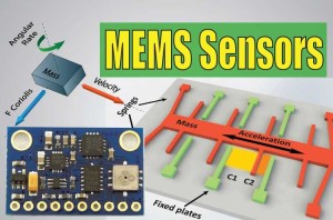
To begin with, let’s take a look how the ADXL345 sensor works. This is a 3-axis accelerometer which can measure both static and dynamic forces of acceleration. The earth gravitational force is a typical example of static force, while dynamic forces can be caused by vibrations, movements and so on.
The unit of measurement for acceleration is meter per second squared (m/s^2). However, accelerometer sensors usually express the measurements in “g” or gravity. One “g” is the value of the earth gravitational force which is equal to 9.8 meters per second squared.
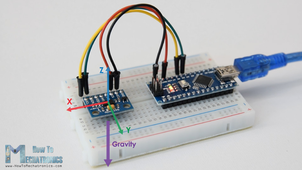
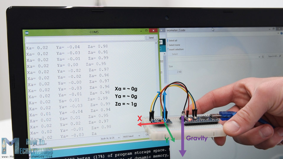
So, if we have an accelerometer positioned flat, with its Z-axis pointing upwards, opposite to the gravitational force, the Z-axis output of the sensor will be 1g. On the other hand, the X and Y outputs will be zero, because the gravitational force is perpendicular to these axes and doesn’t affect them at all.
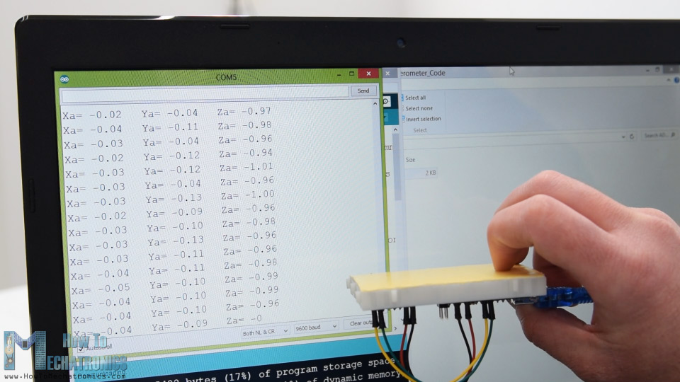
If we flip the sensor upside down, then the Z-axis output will be -1 g. This means that the outputs of the sensor due to its orientation to gravity can vary from -1g to +1g.
So according to this data and using some trigonometry math, we can calculate the angle at which the sensor is positioned.
How to Read ADXL345 Accelerometer Data with Arduino
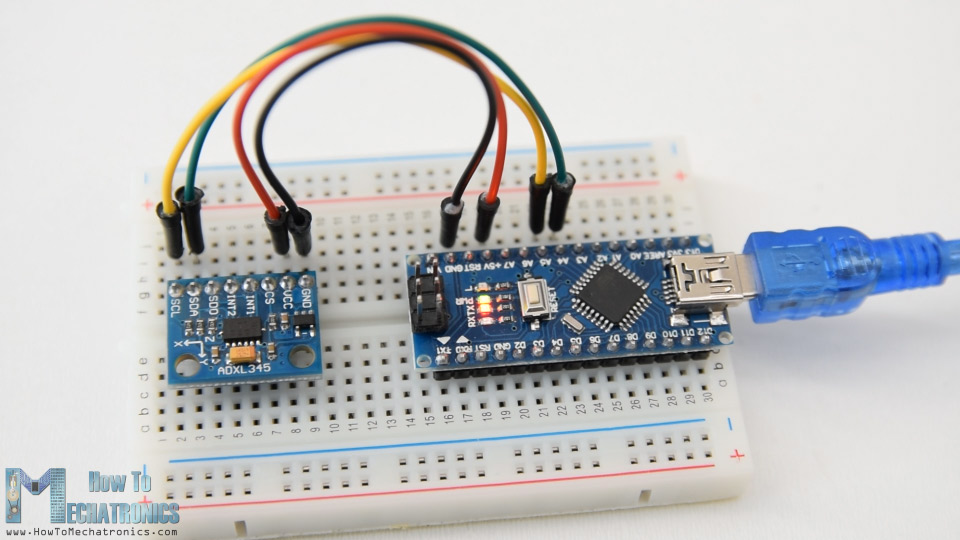
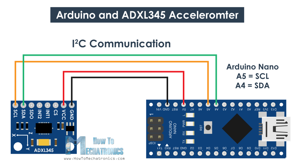
Ok, now let’s see how we can read the ADXL345 accelerometer data using the Arduino. This sensor uses the I2C protocol for communication with the Arduino so we need only two wires for connecting it, plus the two wires for powering it.
You can get the components needed for this Arduino Tutorial from the links below:
- ADXL345 Accelerometer ………………. Amazon / Banggood / AliExpress
- Arduino Board …………………………….. Amazon / Banggood / AliExpress
- Breadboard and Jump Wires ………… Amazon / Banggood / AliExpress
Disclosure: These are affiliate links. As an Amazon Associate I earn from qualifying purchases.
ADXL345 Accelerometer Arduino Code
Here’s the Arduino code fo reading the ADXL345 accelerometer data.
/*
Arduino and ADXL345 Accelerometer Tutorial
by Dejan, https://howtomechatronics.com
*/
#include <Wire.h> // Wire library - used for I2C communication
int ADXL345 = 0x53; // The ADXL345 sensor I2C address
float X_out, Y_out, Z_out; // Outputs
void setup() {
Serial.begin(9600); // Initiate serial communication for printing the results on the Serial monitor
Wire.begin(); // Initiate the Wire library
// Set ADXL345 in measuring mode
Wire.beginTransmission(ADXL345); // Start communicating with the device
Wire.write(0x2D); // Access/ talk to POWER_CTL Register - 0x2D
// Enable measurement
Wire.write(8); // (8dec -> 0000 1000 binary) Bit D3 High for measuring enable
Wire.endTransmission();
delay(10);
}
void loop() {
// === Read acceleromter data === //
Wire.beginTransmission(ADXL345);
Wire.write(0x32); // Start with register 0x32 (ACCEL_XOUT_H)
Wire.endTransmission(false);
Wire.requestFrom(ADXL345, 6, true); // Read 6 registers total, each axis value is stored in 2 registers
X_out = ( Wire.read()| Wire.read() << 8); // X-axis value
X_out = X_out/256; //For a range of +-2g, we need to divide the raw values by 256, according to the datasheet
Y_out = ( Wire.read()| Wire.read() << 8); // Y-axis value
Y_out = Y_out/256;
Z_out = ( Wire.read()| Wire.read() << 8); // Z-axis value
Z_out = Z_out/256;
Serial.print("Xa= ");
Serial.print(X_out);
Serial.print(" Ya= ");
Serial.print(Y_out);
Serial.print(" Za= ");
Serial.println(Z_out);
}Code language: Arduino (arduino)Description: So first we need to include the Wire.h library which is used for the I2C communication. If you want to learn more on how the I2C communication works and how to use it with Arduino you can check my other detailed tutorial for it.
Each device that uses the I2C communication has a unique I2C address, and this address can be found in the datasheet of the sensor (ADXL345 Datasheet). So, once we define the address and the variables for the three outputs, in the setup section, first, we need to initialize the wire library and then set the accelerometer in measuring mode. In order to do that, if we take a look at the datasheet again, we can see that we need to set the bit D3 of the POWER_CTL register HIGH.
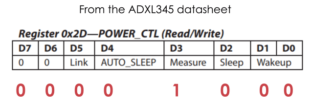
So, using the beginTransmission() function we start the communication, then using the write() function we tell which register we want to access, and again using the write() function we set the D3 bit HIGH, by writing the number 8 in decimal which correspond to setting the bit D3 HIGH.
// Set ADXL345 in measuring mode
  Wire.beginTransmission(ADXL345); // Start communicating with the device
  Wire.write(0x2D); // Access/ talk to POWER_CTL Register - 0x2D
  // Enable measurement
  Wire.write(8); // (8dec -> 0000 1000 binary) Bit D3 High for measuring enable
  Wire.endTransmission();Code language: Arduino (arduino)
In the loop section now we read the data from the sensor. The data for each axis is stored in two bytes or registers. We can see the addresses of these registers from the datasheet.
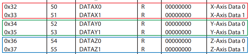
In order to read them all, we start with the first register, and the using the requestionFrom() function we ask to read the 6 registers. Then using the read() function, we read the data from each register, and because the outputs are twos complements we combine them appropriately to get the correct values.
// === Read acceleromter data === //
  Wire.beginTransmission(ADXL345);
  Wire.write(0x32); // Start with register 0x32 (ACCEL_XOUT_H)
  Wire.endTransmission(false);
  Wire.requestFrom(ADXL345, 6, true); // Read 6 registers total, each axis value is stored in 2 registers
  X_out = ( Wire.read()| Wire.read() << 8); // X-axis value
  X_out = X_out/256; //For a range of +-2g, we need to divide the raw values by 256, according to the datasheet
  Y_out = ( Wire.read()| Wire.read() << 8); // Y-axis value
  Y_out = Y_out/256;
  Z_out = ( Wire.read()| Wire.read() << 8); // Z-axis value
  Z_out = Z_out/256;Code language: Arduino (arduino)
The output values from the sensor actually depend on the selected sensitivity, which can vary from +- 2g to +-16g. The default sensitivity is +-2g so that’s why we need to divide the output by 256 in order to get values from -1 to +1g. The 256 LSB/g means that we have 256 counts per g.
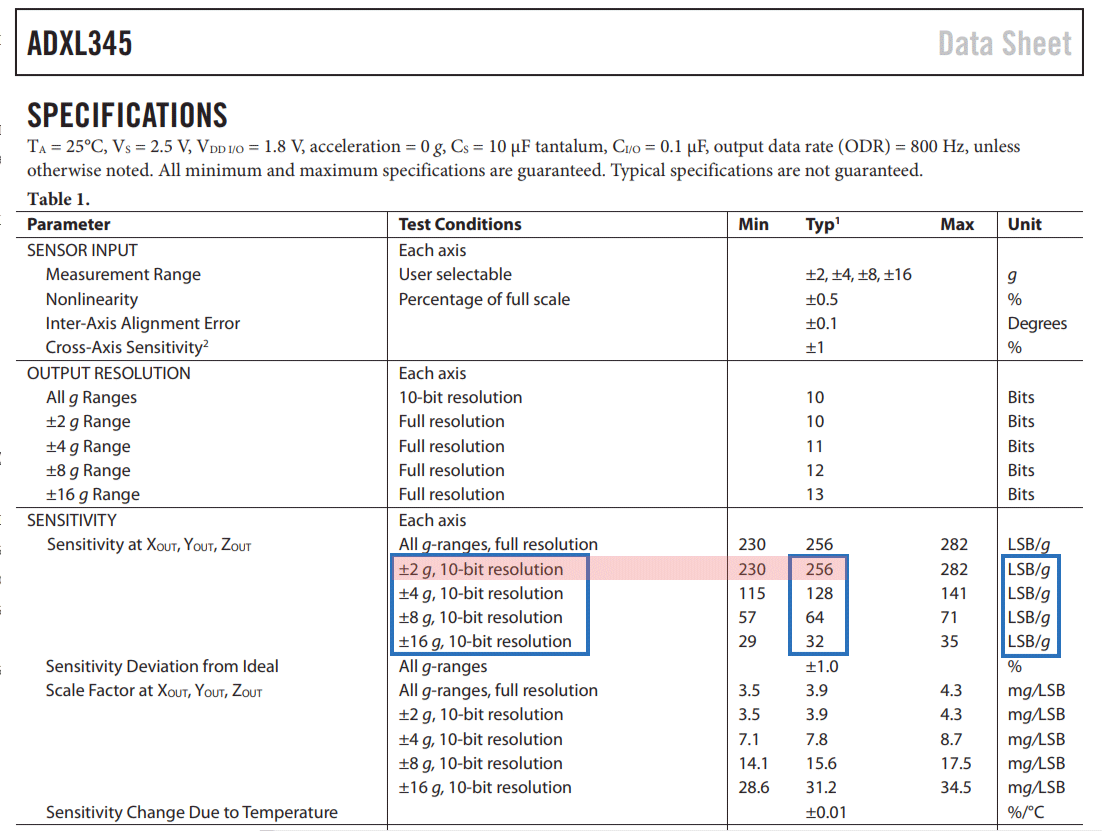
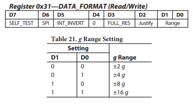
Depending on the application we can select the appropriate sensitivity. In this case, for tracking orientation, +-2g sensitivity is fine, but for application where we need to sense higher acceleration force from like sudden movements, shocks and so on, we can choose some of the other sensitivity ranges using the DATA_FORMAT register and its D1 and D0 bits.
ADXL345 Accelerometer Calibration
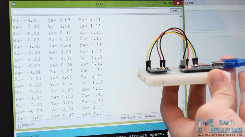
Nevertheless, once we read the data, we can simply print it on the serial monitor to check whether the values are as expected. In my case, the values I was getting were not exactly as they should be, especially the Z-axis which had a noticeable error of 0.1g.
To solve this issue, we need to calibrate the accelerometer using the 3 offset calibration registers, and here’s how we can do that. So, we need to position the sensor flat, and print the RAW values without dividing them by 256.

From here now we can notice the how much the outputs are off, in my case, the Z output was around 283. That’s difference of 27 in positive. Now we need to divide this value by 4, and that will give use the number that we need to write to the Z-axis offset register. If we upload the code now, the Z-axis output will be exactly 256, or 1g as it should be.
// This code goes in the SETUP section
// Off-set Calibration
  //X-axis
  Wire.beginTransmission(ADXL345);
  Wire.write(0x1E);  // X-axis offset register
  Wire.write(1);
  Wire.endTransmission();
  delay(10);
  //Y-axis
  Wire.beginTransmission(ADXL345);
  Wire.write(0x1F); // Y-axis offset register
  Wire.write(-2);
  Wire.endTransmission();
  delay(10);

  //Z-axis
  Wire.beginTransmission(ADXL345);
  Wire.write(0x20); // Z-axis offset register
  Wire.write(-7);
  Wire.endTransmission();
  delay(10);Code language: Arduino (arduino)
If needed we should calibrate the other axis using the same method. And just a quick note that this calibration is not permanently written to the registers. We need to do write these values to the registers at each power up of the sensor.
Once we are done with the calibration, we can now finally calculate the Roll and Pitch, or the rotation around the X-axis and the rotation around the Y axis in degrees, using these two formulas.
// Calculate Roll and Pitch (rotation around X-axis, rotation around Y-axis)
  roll = atan(Y_out / sqrt(pow(X_out, 2) + pow(Z_out, 2))) * 180 / PI;
  pitch = atan(-1 * X_out / sqrt(pow(Y_out, 2) + pow(Z_out, 2))) * 180 / PI;Code language: Arduino (arduino)
For more details how these formulas work, you can check this Freescale Semiconductor application note.
Arduino and ADXL345 Accelerometer Orientation Tracking – 3D Visualization
Ok, let’s make the accelerometer 3D visualization example now.
So, we are using the same code, which sends the Roll and Pitch values through the serial port. Here’s the complete Arduino code:
/*
    Arduino and ADXL345 Accelerometer - 3D Visualization Example
     by Dejan, https://howtomechatronics.com
*/
#include <Wire.h>  // Wire library - used for I2C communication

int ADXL345 = 0x53; // The ADXL345 sensor I2C address

float X_out, Y_out, Z_out;  // Outputs
float roll,pitch,rollF,pitchF=0;

void setup() {
  Serial.begin(9600); // Initiate serial communication for printing the results on the Serial monitor

  Wire.begin(); // Initiate the Wire library
  // Set ADXL345 in measuring mode
  Wire.beginTransmission(ADXL345); // Start communicating with the device
  Wire.write(0x2D); // Access/ talk to POWER_CTL Register - 0x2D
  // Enable measurement
  Wire.write(8); // Bit D3 High for measuring enable (8dec -> 0000 1000 binary)
  Wire.endTransmission();
  delay(10);

  //Off-set Calibration
  //X-axis
  Wire.beginTransmission(ADXL345);
  Wire.write(0x1E);
  Wire.write(1);
  Wire.endTransmission();
  delay(10);
  //Y-axis
  Wire.beginTransmission(ADXL345);
  Wire.write(0x1F);
  Wire.write(-2);
  Wire.endTransmission();
  delay(10);

  //Z-axis
  Wire.beginTransmission(ADXL345);
  Wire.write(0x20);
  Wire.write(-9);
  Wire.endTransmission();
  delay(10);
}

void loop() {
  // === Read acceleromter data === //
  Wire.beginTransmission(ADXL345);
  Wire.write(0x32); // Start with register 0x32 (ACCEL_XOUT_H)
  Wire.endTransmission(false);
  Wire.requestFrom(ADXL345, 6, true); // Read 6 registers total, each axis value is stored in 2 registers
  X_out = ( Wire.read() | Wire.read() << 8); // X-axis value
  X_out = X_out / 256; //For a range of +-2g, we need to divide the raw values by 256, according to the datasheet
  Y_out = ( Wire.read() | Wire.read() << 8); // Y-axis value
  Y_out = Y_out / 256;
  Z_out = ( Wire.read() | Wire.read() << 8); // Z-axis value
  Z_out = Z_out / 256;

  // Calculate Roll and Pitch (rotation around X-axis, rotation around Y-axis)
  roll = atan(Y_out / sqrt(pow(X_out, 2) + pow(Z_out, 2))) * 180 / PI;
  pitch = atan(-1 * X_out / sqrt(pow(Y_out, 2) + pow(Z_out, 2))) * 180 / PI;

  // Low-pass filter
  rollF = 0.94 * rollF + 0.06 * roll;
  pitchF = 0.94 * pitchF + 0.06 * pitch;

  Serial.print(rollF);
  Serial.print("/");
  Serial.println(pitchF);
}Code language: Arduino (arduino)
Now in the Processing development environment we need to receive these values and use them to rotate the 3D object that we will create. Here’s the complete Processing code:
/*
    Arduino and ADXL345 Accelerometer - 3D Visualization Example
     by Dejan, https://howtomechatronics.com
*/

import processing.serial.*;
import java.awt.event.KeyEvent;
import java.io.IOException;

Serial myPort;

String data="";
float roll, pitch;

void setup() {
  size (960, 640, P3D);
  myPort = new Serial(this, "COM8", 9600); // starts the serial communication
  myPort.bufferUntil('\n');
}

void draw() {
  translate(width/2, height/2, 0);
  background(33);
  textSize(22);
  text("Roll: " + int(roll) + "     Pitch: " + int(pitch), -100, 265);

  // Rotate the object
  rotateX(radians(roll));
  rotateZ(radians(-pitch));

  // 3D 0bject
  textSize(30);
  fill(0, 76, 153);
  box (386, 40, 200); // Draw box
  textSize(25);
  fill(255, 255, 255);
  text("www.HowToMechatronics.com", -183, 10, 101);

  //delay(10);
  //println("ypr:\t" + angleX + "\t" + angleY); // Print the values to check whether we are getting proper values
}

// Read data from the Serial Port
void serialEvent (Serial myPort) {
  // reads the data from the Serial Port up to the character '.' and puts it into the String variable "data".
  data = myPort.readStringUntil('\n');

  // if you got any bytes other than the linefeed:
  if (data != null) {
    data = trim(data);
    // split the string at "/"
    String items[] = split(data, '/');
    if (items.length > 1) {

      //--- Roll,Pitch in degrees
      roll = float(items[0]);
      pitch = float(items[1]);
    }
  }
}Code language: Arduino (arduino)
Description: So here, we need to include the serial library, define the serial port and the baud rate which needs to match we the baud rate of the uploaded Arduino sketch. Then we read the incoming data and put it into the appropriate roll and pitch variables. In the main draw loop, we use these values to rotate the 3D object, and in this case that’s a simple box with has a particular color and a text on it.
If we run the sketch, the 3D object will appear and it will track the orientation of the accelerometer sensor. We can notice here that the object is actually a bit shaky and that’s because the accelerometer captures not just the gravitational force, but also small forces generated by the movements of our hand. In order to get smoother result, we can use a simple Low-pass filter. Here I implemented such a filter in the Arduino code, which it takes 94% of the previous state and adds 6% of the current state or angle.
// Low-pass filter
  rollF = 0.94 * rollF + 0.06 * roll;
  pitchF = 0.94 * pitchF + 0.06 * pitch;Code language: Arduino (arduino)
With this filter, we can notice that the object moves a lot smoother now, but there is also a side effect and that’s slower responsiveness. We can also notice that we are missing the Yaw, or rotation around the Z-axis. Using only the 3-axis accelerometer data we are not able to calculate the Yaw.
In order to do that and improve the overall performance of our orientation tracking sensor, we actually need to include an additional sensor, a gyroscope, and fuse its data with the accelerometer.
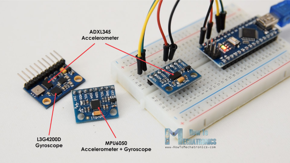
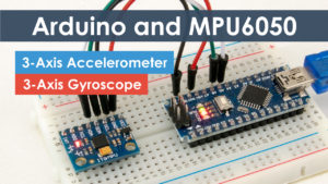
So, we can either use the ADXL345 accelerometer in combination some gyroscope sensor, or use the MPU6050 IMU which has both 3-Axis accelerometer and 3-Axis gyroscope integrated on a single chip. You can find more detailed tutorial on this sensor in my next video.
I hope you enjoyed this tutorial and learned something new. Feel free to ask any question in the comments section below and don’t forget to check my collection of Arduino Projects.
A well detailed guide 🙂 Nevertheless, some questions came to mind when reading the part about the low pass filter: I learned at school that a low pass filter is something like H(p)=S(p)/E(p)=K/(1+T*p) with K=1 so the error is null that we could discretize( s(k+1) =s(k)+[K*e(k)-s(k)]*[t(k+1)-t(k)]/T where T=1/Wc => s(k+1) =s(k)*[1-[t(k+1)-t(k)]/T]+[ K*[t(k+1)-t(k)]/T ] * e(k) ). You have s(k+1) = 0.94 * s(k) + 0.06 * e(k), so [t(k+1)-t(k)]/T=0.06, and t(k+1)-t(k)=1/9600=0.0001 is given by the bode rate[9600 information are send every second ] (if there is no “delay” in the arduino code) which means T=0.0001/0.06~0.001. So now that we have all the variables, we should have the t5%=3*T=0.003 s ( for an order 1 filter). Nevertheless, i got a t5% of about 3s with the serial monitor. I don’t know where i made a mistake :'(
In addition i have another question which this time is about a high pass filter this time to filter the continuous part of the filter: The adxl345 doesn’t have enough variables to resolve the space problem, but can’t we just subtract cos(theta) on one axis and sin(theta) on the other one if we only do it into a plane one?
Well it was great to learn new things. I look forward to the other tutorial 🙂
ps: sorry if i make mistake when writing
Nice article, just one question; how can I take the resulting data and send it via radio waves?
Thanks! Well check my NRF24L01 tutorial, as well as my DIY RC Transmitter project, you will find more info how you can do that in there.
Very helpful. Thank you.
For anyone interested more in calibration follow this doc…
AN-1077: ADXL345 Quick Start Guide – Analog Devices
Thank you so much, very complete and informative!
A very useful article, which is very easy to understand, is expected to use GY-85 IMU to add Kalman filter to do an action recognition.And how to save the real-data in excel.
Hey, you can try to use complementary filter, it’s easier to implement and it provides more results.
A really cool article. I learned a lot how to generate data about the orientation in arduino with this. The only thing there I even do not understand is how to reproduce the real time data in a 3D display. Need to download another software or the code by it self do the importation of the resourse?
Hey, thanks! Well for the 3D visualization example you need the Processing IDE.
Very professional and informative on the adxl. I would like to see an explanation of using the adxl and controlling a servo and/or stepper contingent upon the output of the adxl. e.g. if the adxl rotates left, the servo/stepper would rotate right to compensate. Thanks and keep up the good work.
Thanks! Well such a example will be covered in the next tutorial for the MPU6050 Accelerometer and Gyro module.