In tutorial we will learn how to build a DIY Arduino RC transmitter. Very often I need wireless control for the projects that I make, so therefore I built this multifunctional radio controller which can be used for pretty much everything.
You can watch the following video or read the written tutorial below.
Overview
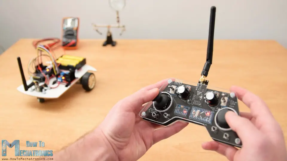
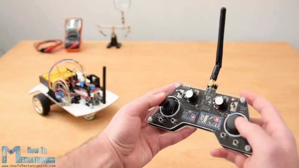
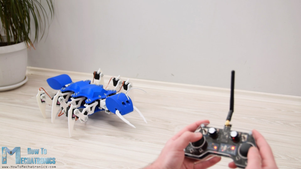
Now I can wirelessly control any Arduino project with just some small adjustments at the receiver side. This transmitter can be also used as any commercial RC transmitter for controlling RC toys, cars, drones and so on. For that purpose it just needs a simple Arduino receiver which then generates the appropriate signals for controlling those commercial RC devices.
I will explain how everything works in this video through few examples of controlling an Arduino robot car, controlling the Arduino Ant Robot from my previous video and controlling a brushless DC motor using an ESC and some servo motors.
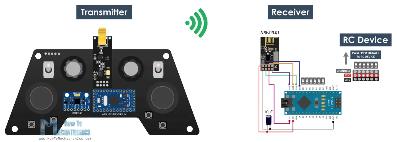
The radio communication of this controller is based on the NRF24L01 transceiver module which if used with an amplified antenna it can have a stable range of up to 700 meters in open space. It features 14 channels, 6 of which are analog inputs and 8 digital inputs.
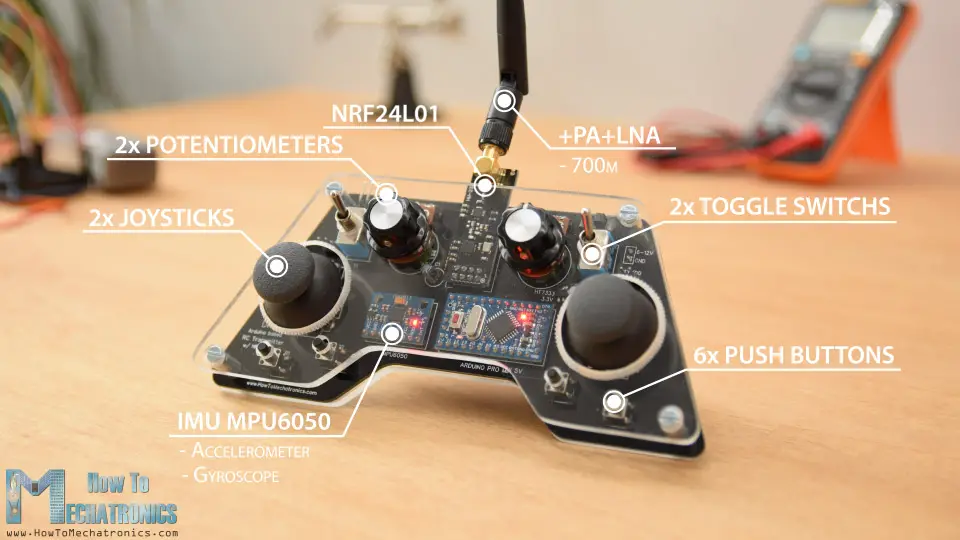
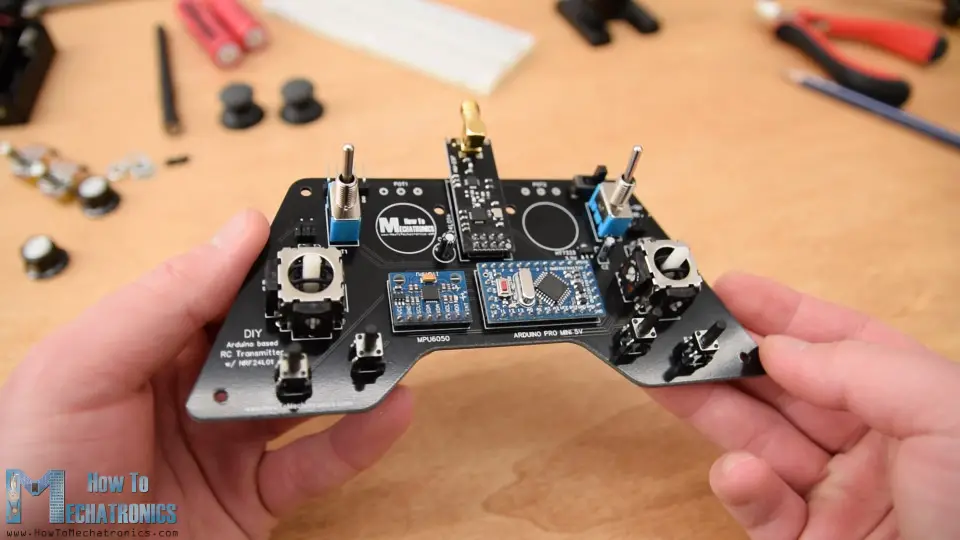
It has two joysticks, two potentiometers, two toggle switches, six buttons and additionally an internal measuring unit consisting of an accelerometer and a gyroscope which can be also used for controlling things with just moving around or tilting the controller.
Arduino RC Transmitter Circuit Diagram
To begin with, let’s take a look at the circuit diagram. The brain of this RC controller is an Arduino Pro Mini which is powered using 2 LiPo batteries producing around 7.4 volts. We can connect them directly to the RAW pin of the Pro Mini which has a voltage regulator that reduced the voltage to 5V. Note that there are two versions of the Arduino Pro Mini, like the one I have that operates at 5V and the other operates at 3.3V.
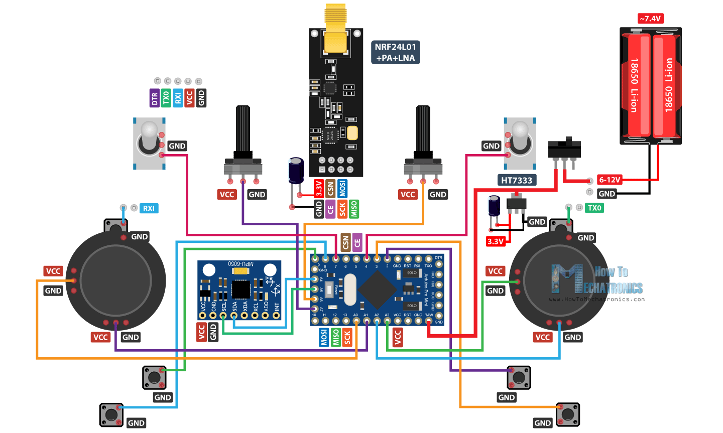
On the other hand, the NRF24L01 module strictly needs 3.3V and it’s recommended to come from a dedicated source. Therefore we need to use a 3.3V voltage regulator which is connected to the batteries and convert the 7.4V to 3.3V. Also we need to use a decoupling capacitor right next to the module in order to keep the voltage more stable, thus the radio communication will be more stable as well. The NRF24L01 module communicates with the Arduino using SPI protocol, while the MPU6050 accelerometer and gyro module uses the I2C protocol.
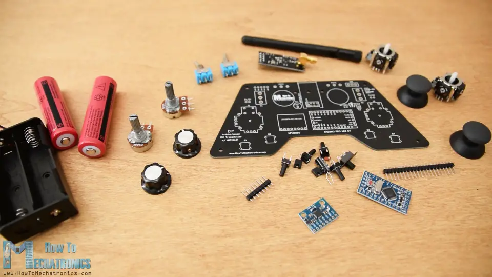
You can get the components needed for this Arduino Tutorial from the links below:
- NRF24L01 Transceiver Module……….. Amazon / Banggood / AliExpress
- NRF24L01 + PA + LNA ……………………. Amazon / Banggood / AliExpress
- Potentiometer ……………………………….. Amazon / Banggood / AliExpress
- Servo Motor …………………………………… Amazon / Banggood / AliExpress
- Toggle Switch …………………………….….. Amazon / Banggood / AliExpress
- Joystick ………………………………………….. Amazon / Banggood / AliExpress – this Joystick comes with a breakout board so you will have to desolder the Joystick from it
- Joystick without breakout board ………… Ebay
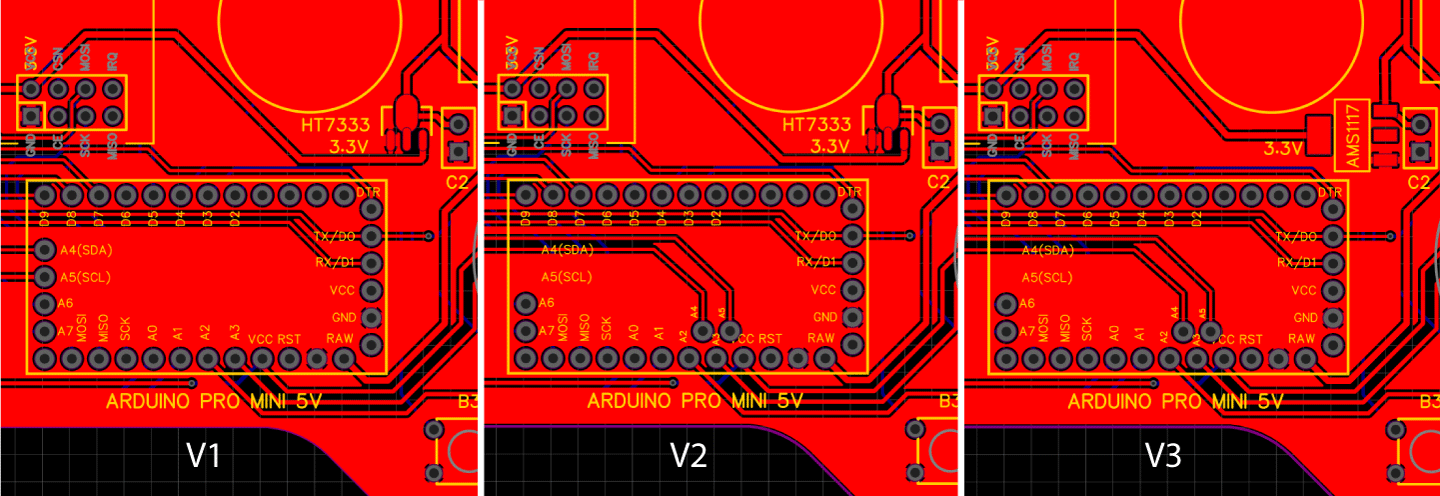
- Arduino Pro Mini…………………………….. Amazon / Banggood / AliExpress– You need PCB V2 or V3 version for this boards
- Arduino Pro Mini like the one I used….. Ebay– PCB V1
- HT7333 3.3v voltage regulator ……………. From local electronic shop – PCB V1 & PCB V2
- AMS1117 3.3v voltage regulator …………… Amazon / Banggoood / AliExpress – PCB V3
Disclosure: These are affiliate links. As an Amazon Associate I earn from qualifying purchases.
PCB Design
I actually ended up utilizing all analog and digital pins of the Arduino Pro Mini. So now if I try to connect everything together using jump wires it will be quite a mess. Therefore I designed a custom PCB using the EasyEDA free online circuit design software.
Here I took into consideration the ergonomics of the controller and designed it to be easily held by two hands, while all controls are within the range of the fingers. I made the edges round and added some 3mm holes so I can mount the PCB onto something later. I placed the pins for programming the Arduino Pro Mini at the top side of the controller so they can be easily accessed in case we want to reprogram the Arduino. We can also notice here that I used the RX and TX pins of the Arduino for the joystick buttons. However these two lines needs to be disconnected from anything while we are uploading the sketch to the Arduino. So therefore they are interrupted with two pins which can be then easily connected using simple jumper caps.
Please note: Make sure you have the right Arduino Pro Mini version to mach the PCB or modify the PCB design according to it. Here’s a comparison photo between the three different versions, depending on your Arduino and the voltage regulator.
Here’s a link to the project files of this PCB design. These opens the three different version in separate tabs, so you can choose the one you need.
So once I finished the design, I generated the Gerber file needed for manufacturing the PCB.
Gerber file:
Then I ordered the PCB from JLCPCB which are also the sponsor of this video.

Here we can simply drag and drop the Gerber file and once uploaded, we can review our PCB in the Gerber viewer. If everything is all right then we can go on and select the properties that we want for our PCB. This time I chose the PCB color to be black. And that’s it, now we can simply order our PCB at a reasonable price. Note that if it’s your first order from JLCPCB, you can get up to 10 PCBs for only $2.
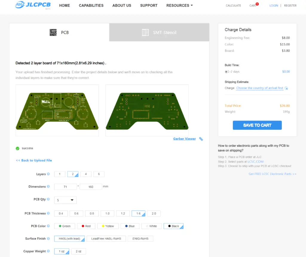
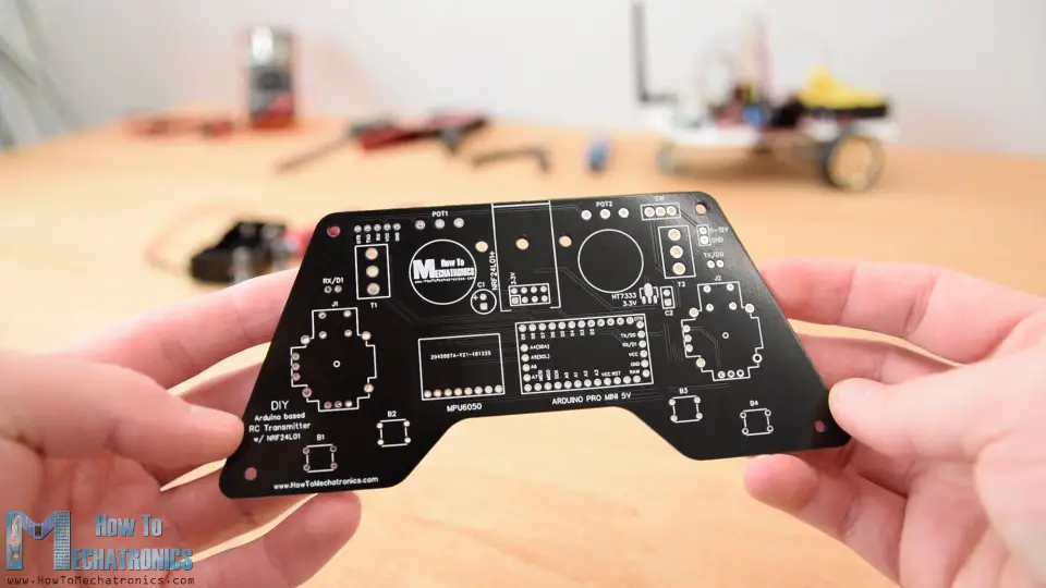
And here it is. I just really love how this PCB turned out in this black color. The quality of the PCB is great, and everything is exactly the same as in the design.
Assembling the PCB
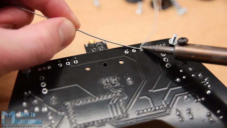
Ok now we can move on with assembling the PCB. I started with a soldering the pin headers of the Arduino Pro Mini. An easy and good way to do that is to place them onto a breadboard and so they will stay firmly in place while soldering.
The Pro Mini also have pins on the sides, but note that these pins location might vary depending on the manufacturer.
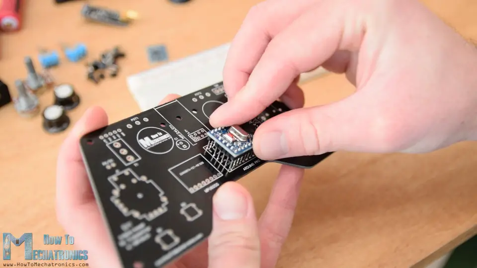
For the particular model that I have, I need 5 pins for each side, while leaving one GND pin empty because I used its area below on the PCB for running some traces. I soldered the Arduino Pro Mini directly onto the PCB and cut the execs length of the headers. Right next to it goes the MPU6050 accelerometer and gyroscope module.
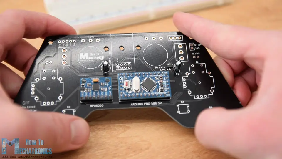
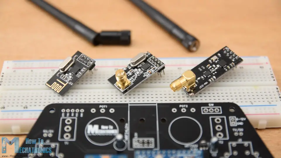
Then I soldered the 3.3V voltage regulator with a capacitor next to it, and another capacitor near the NRF24L01 module. This module have three different versions and we can use any of them here.
I continued with the pins for programming the Arduino, the RX and TX pins, the power supply pins and the power switch.
Next for soldering the potentiometers to the PCB I had to extend their pins using some pin headers.
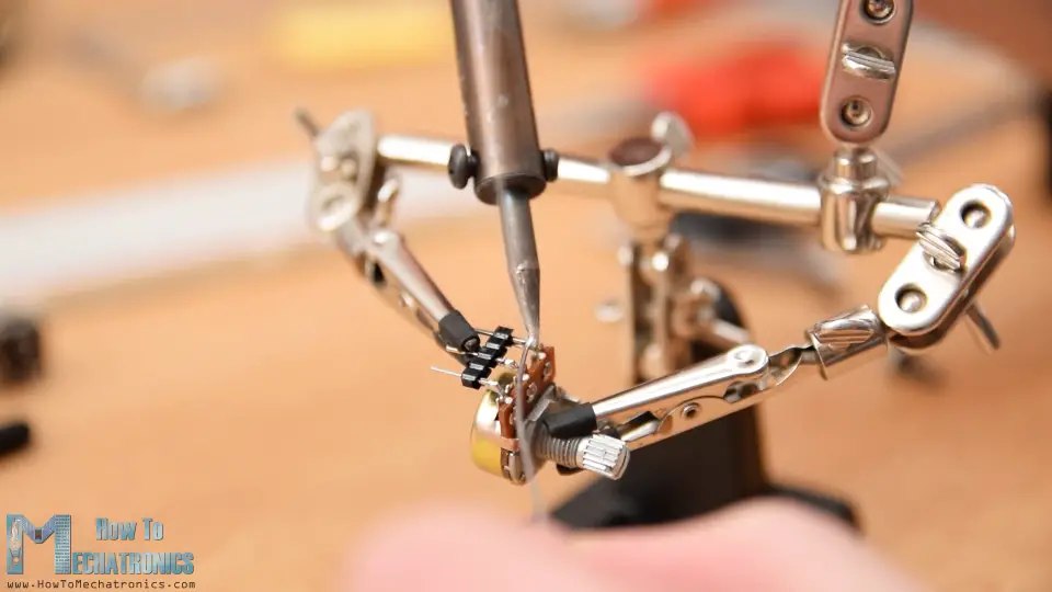
We can note here that I previously cut the length of the knobs so I can properly fit some caps onto them. However, we will solder the potentiometers to the PCB a bit later.
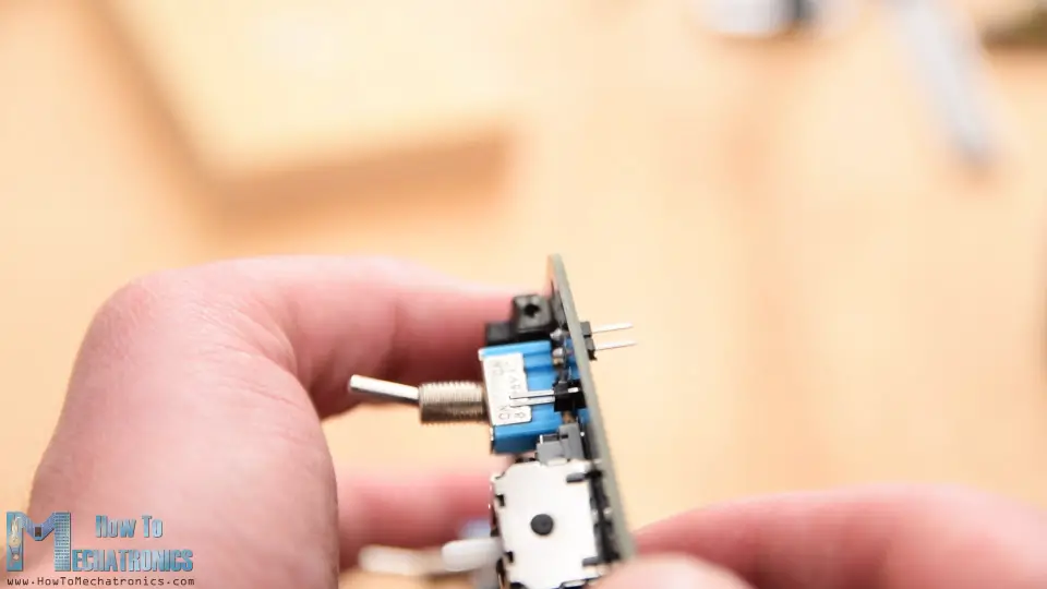
Then I inserted and soldered the two toggle switches and the two joysticks in place.
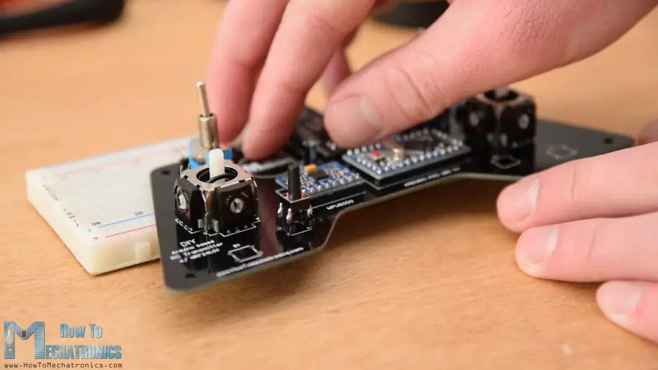
Finally what’s left is to solder the four push buttons. However they don’t have the proper height, so again I used pin headers to extend their pins a little bit.
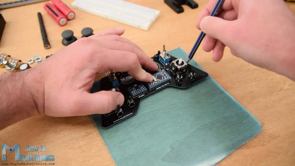
And that’s it, our PCB is now ready so we can continue with making the cover for it. Because I like how the PCB looks and I want to be visible I decided to use transparent acrylic for the cover.
Here I have 4 mm tick transparent acrylic which currently have a protective foil and appears to be blue. The idea for the cover is to make two plates with the shape of the PCB and secure one of them at the top side and the other at the bottom side of the PCB.
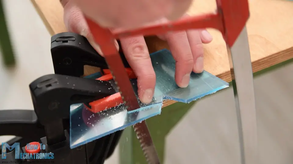
So I marked PCB shape and using a metal hand saw I cut the acrylic according to it.
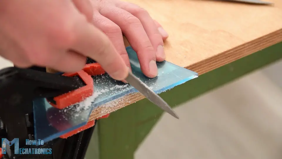
Then using a simple rasp I fine-tuned the shape of the acrylic. The two plates came out great and they perfectly match with the PCB.
Next I marked the locations where I need to make openings for the components to pass through. Using a 3mm drill I first made the 4 holes for securing the plates to the PCB. For these holes I also made counter sinks so that the bolts can be placed flash with the plates.
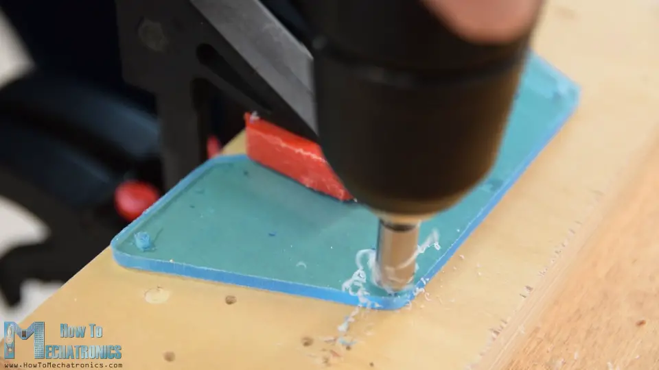
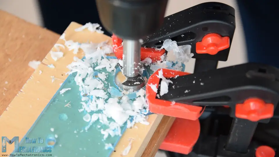
For the openings for the toggle switches and the potentiometers I used 6mm drill, and for the joystick openings I used 25mm Forstner bit. Again, using a rasp, I fine-tuned all the openings.
Before assembling the cover, just a quite note that I actually soldered the pin header for the power supply upside down so it can be reached from the back side where the battery will be located.
Ok now we can start with assembling the cover. I started with peeling off the protective foil from the acrylic which I must admit was quite satisfying because the acrylic was so clean now. So first I secured the two potentiometers on the top plate, inserted the 3mm mounting bolts and placed the 11mm distance rings in place.
Then I carefully merged and secured the top plate and the PCB using some bolts. At this point I finally soldered the potentiometers to the PCB because earlier I didn’t know exactly at what height they will be placed.
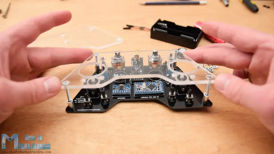
Next on the back plate I attached the battery holder using 2 bolts. I finished the cover assembly by securing the back plate to the back side of the PCB using the four mounting bolts.
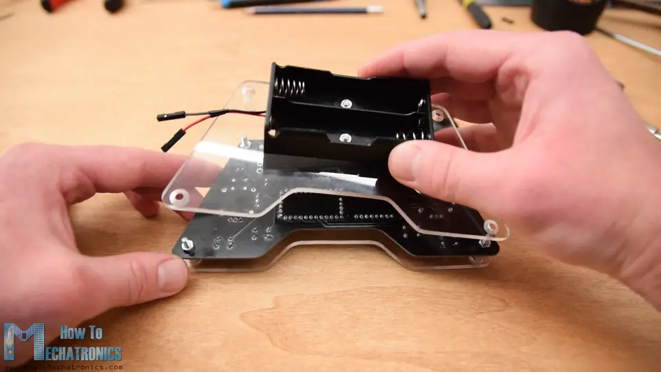
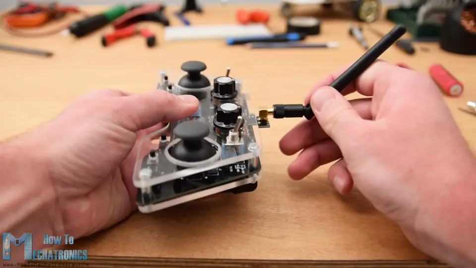
Finally, we can attach the battery lines to the power supply pins, insert and secure the knobs on the potentiometers, insert the joysticks knobs and attach the antenna to the NRF24l01 module. And that’s it, we are finally done with the DIY Arduino RC transmitter.
What’s left now is to program the Arduino. For programming a Pro Mini board we need an USB to serial UART interface which can be hooked up to the programing header located on the top side of our controller.
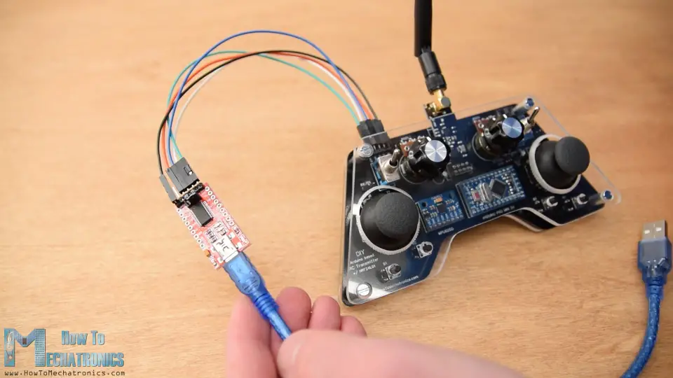
Then in the Arduino IDE tools menu we need to select the Arduino Pro or Pro Mini board, select the proper version of the processor, select the port and select the programming method to “USBasp”.
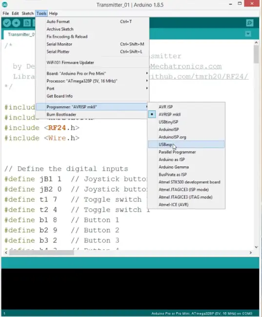
And so now we are able to upload the code to the Arduino.
DIY Arduino based RC Transmitter Code
Let’s explain how the transmitter code works. So first we need to include the SPI and RF24 library for the wireless communication, and the I2C library for the accelerometer module. Then we need to define the digital inputs, some variables needed for the program below, define the radio object and the communication address.
#include <SPI.h>
#include <nRF24L01.h>
#include <RF24.h>
#include <Wire.h>
// Define the digital inputs
#define jB1 1 // Joystick button 1
#define jB2 0 // Joystick button 2
#define t1 7 // Toggle switch 1
#define t2 4 // Toggle switch 1
#define b1 8 // Button 1
#define b2 9 // Button 2
#define b3 2 // Button 3
#define b4 3 // Button 4
const int MPU = 0x68; // MPU6050 I2C address
float AccX, AccY, AccZ;
float GyroX, GyroY, GyroZ;
float accAngleX, accAngleY, gyroAngleX, gyroAngleY;
float angleX, angleY;
float AccErrorX, AccErrorY, GyroErrorX, GyroErrorY;
float elapsedTime, currentTime, previousTime;
int c = 0;
RF24 radio(5, 6); // nRF24L01 (CE, CSN)
const byte address[6] = "00001"; // AddressCode language: Arduino (arduino)Then we need to define a structure where we will store the 14 input values of the controller. The maximum size of this structure can be 32 bytes because that’s the NRF24L01 buffer limit or the amount of data the module can send at once.
/ Max size of this struct is 32 bytes - NRF24L01 buffer limit
struct Data_Package {
  byte j1PotX;
  byte j1PotY;
  byte j1Button;
  byte j2PotX;
  byte j2PotY;
  byte j2Button;
  byte pot1;
  byte pot2;
  byte tSwitch1;
  byte tSwitch2;
  byte button1;
  byte button2;
  byte button3;
  byte button4;
};

Data_Package data; //Create a variable with the above structureCode language: Arduino (arduino)
In the setup section we need to initialize the MPU6050 module and we can also calculate the IMU error which is a values that is later used when calculating the correct angles of the module.
void initialize_MPU6050() {
  Wire.begin();                      // Initialize comunication
  Wire.beginTransmission(MPU);       // Start communication with MPU6050 // MPU=0x68
  Wire.write(0x6B);                  // Talk to the register 6B
  Wire.write(0x00);                  // Make reset - place a 0 into the 6B register
  Wire.endTransmission(true);        //end the transmission
  // Configure Accelerometer
  Wire.beginTransmission(MPU);
  Wire.write(0x1C);                  //Talk to the ACCEL_CONFIG register
  Wire.write(0x10);                  //Set the register bits as 00010000 (+/- 8g full scale range)
  Wire.endTransmission(true);
  // Configure Gyro
  Wire.beginTransmission(MPU);
  Wire.write(0x1B);                   // Talk to the GYRO_CONFIG register (1B hex)
  Wire.write(0x10);                   // Set the register bits as 00010000 (1000dps full scale)
  Wire.endTransmission(true);
}Code language: Arduino (arduino)
You can find more details how MEMS accelerometer and gyro work here. A dedicated tutorial for the MPU6050 is coming soon.
Then we need to initialize the radio communication, activate the Arduino internal pull-up resistors for all digital inputs and set the initial default values for all variables.
// Define the radio communication
  radio.begin();
  radio.openWritingPipe(address);
  radio.setAutoAck(false);
  radio.setDataRate(RF24_250KBPS);
  radio.setPALevel(RF24_PA_LOW);

  // Activate the Arduino internal pull-up resistors
  pinMode(jB1, INPUT_PULLUP);
  pinMode(jB2, INPUT_PULLUP);
  pinMode(t1, INPUT_PULLUP);
  pinMode(t2, INPUT_PULLUP);
  pinMode(b1, INPUT_PULLUP);
  pinMode(b2, INPUT_PULLUP);
  pinMode(b3, INPUT_PULLUP);
  pinMode(b4, INPUT_PULLUP);Code language: Arduino (arduino)
In the loop section start by reading the all analog inputs, map their values from 0 to 1023 into byte values from 0 to 255 because we already defined the variables in our structure as bytes. Each input is stored in the particular data variable from the structure.
// Read all analog inputs and map them to one Byte value
  data.j1PotX = map(analogRead(A1), 0, 1023, 0, 255); // Convert the analog read value from 0 to 1023 into a BYTE value from 0 to 255
  data.j1PotY = map(analogRead(A0), 0, 1023, 0, 255);
  data.j2PotX = map(analogRead(A2), 0, 1023, 0, 255);
  data.j2PotY = map(analogRead(A3), 0, 1023, 0, 255);
  data.pot1 = map(analogRead(A7), 0, 1023, 0, 255);
  data.pot2 = map(analogRead(A6), 0, 1023, 0, 255);Code language: Arduino (arduino)
We should just note that because we use the pull-up resistors the digital pins readings are 0 when the buttons are pressed.
// Read all digital inputs
  data.j1Button = digitalRead(jB1);
  data.j2Button = digitalRead(jB2);
  data.tSwitch2 = digitalRead(t2);
  data.button1 = digitalRead(b1);
  data.button2 = digitalRead(b2);
  data.button3 = digitalRead(b3);
  data.button4 = digitalRead(b4);Code language: Arduino (arduino)
So using the radio.write() function we simple send the values from all 14 channels to the receiver.
// Send the whole data from the structure to the receiver
  radio.write(&data, sizeof(Data_Package));Code language: Arduino (arduino)
In case the toggle switch 1 is switched on, then we use the accelerometer and gyro data instead for the control.
if (digitalRead(t1) == 0) {
    read_IMU();    // Use MPU6050 instead of Joystick 1 for controling left, right, forward and backward movements
  }Code language: Arduino (arduino)
So instead of the joystick 1 X and Y values we are using the angle values we are getting from the IMU, which we previously convert them from values from -90 to +90 degrees into byte values from 0 to 255 appropriately.
// Map the angle values from -90deg to +90 deg into values from 0 to 255, like the values we are getting from the Joystick
  data.j1PotX = map(angleX, -90, +90, 255, 0);
  data.j1PotY = map(angleY, -90, +90, 0, 255);Code language: Arduino (arduino)
So that’s how the transmitter code, the most important things were defining the radio communication and sending the data to the receiver.
Here’s the complete Arduino code for this DIY Arduino RC Transmitter:
/*
        DIY Arduino based RC Transmitter
  by Dejan Nedelkovski, www.HowToMechatronics.com
  Library: TMRh20/RF24, https://github.com/tmrh20/RF24/
*/

#include <SPI.h>
#include <nRF24L01.h>
#include <RF24.h>
#include <Wire.h>


// Define the digital inputs
#define jB1 1  // Joystick button 1
#define jB2 0  // Joystick button 2
#define t1 7   // Toggle switch 1
#define t2 4   // Toggle switch 1
#define b1 8   // Button 1
#define b2 9   // Button 2
#define b3 2   // Button 3
#define b4 3   // Button 4

const int MPU = 0x68; // MPU6050 I2C address
float AccX, AccY, AccZ;
float GyroX, GyroY, GyroZ;
float accAngleX, accAngleY, gyroAngleX, gyroAngleY;
float angleX, angleY;
float AccErrorX, AccErrorY, GyroErrorX, GyroErrorY;
float elapsedTime, currentTime, previousTime;
int c = 0;


RF24 radio(5, 6);   // nRF24L01 (CE, CSN)
const byte address[6] = "00001"; // Address

// Max size of this struct is 32 bytes - NRF24L01 buffer limit
struct Data_Package {
  byte j1PotX;
  byte j1PotY;
  byte j1Button;
  byte j2PotX;
  byte j2PotY;
  byte j2Button;
  byte pot1;
  byte pot2;
  byte tSwitch1;
  byte tSwitch2;
  byte button1;
  byte button2;
  byte button3;
  byte button4;
};

Data_Package data; //Create a variable with the above structure

void setup() {
  Serial.begin(9600);

  // Initialize interface to the MPU6050
  initialize_MPU6050();

  // Call this function if you need to get the IMU error values for your module
  //calculate_IMU_error();

  // Define the radio communication
  radio.begin();
  radio.openWritingPipe(address);
  radio.setAutoAck(false);
  radio.setDataRate(RF24_250KBPS);
  radio.setPALevel(RF24_PA_LOW);

  // Activate the Arduino internal pull-up resistors
  pinMode(jB1, INPUT_PULLUP);
  pinMode(jB2, INPUT_PULLUP);
  pinMode(t1, INPUT_PULLUP);
  pinMode(t2, INPUT_PULLUP);
  pinMode(b1, INPUT_PULLUP);
  pinMode(b2, INPUT_PULLUP);
  pinMode(b3, INPUT_PULLUP);
  pinMode(b4, INPUT_PULLUP);

  // Set initial default values
  data.j1PotX = 127; // Values from 0 to 255. When Joystick is in resting position, the value is in the middle, or 127. We actually map the pot value from 0 to 1023 to 0 to 255 because that's one BYTE value
  data.j1PotY = 127;
  data.j2PotX = 127;
  data.j2PotY = 127;
  data.j1Button = 1;
  data.j2Button = 1;
  data.pot1 = 1;
  data.pot2 = 1;
  data.tSwitch1 = 1;
  data.tSwitch2 = 1;
  data.button1 = 1;
  data.button2 = 1;
  data.button3 = 1;
  data.button4 = 1;
}
void loop() {
  // Read all analog inputs and map them to one Byte value
  data.j1PotX = map(analogRead(A1), 0, 1023, 0, 255); // Convert the analog read value from 0 to 1023 into a BYTE value from 0 to 255
  data.j1PotY = map(analogRead(A0), 0, 1023, 0, 255);
  data.j2PotX = map(analogRead(A2), 0, 1023, 0, 255);
  data.j2PotY = map(analogRead(A3), 0, 1023, 0, 255);
  data.pot1 = map(analogRead(A7), 0, 1023, 0, 255);
  data.pot2 = map(analogRead(A6), 0, 1023, 0, 255);
  // Read all digital inputs
  data.j1Button = digitalRead(jB1);
  data.j2Button = digitalRead(jB2);
  data.tSwitch2 = digitalRead(t2);
  data.button1 = digitalRead(b1);
  data.button2 = digitalRead(b2);
  data.button3 = digitalRead(b3);
  data.button4 = digitalRead(b4);
  // If toggle switch 1 is switched on
  if (digitalRead(t1) == 0) {
    read_IMU();    // Use MPU6050 instead of Joystick 1 for controling left, right, forward and backward movements
  }
  // Send the whole data from the structure to the receiver
  radio.write(&data, sizeof(Data_Package));
}

void initialize_MPU6050() {
  Wire.begin();                      // Initialize comunication
  Wire.beginTransmission(MPU);       // Start communication with MPU6050 // MPU=0x68
  Wire.write(0x6B);                  // Talk to the register 6B
  Wire.write(0x00);                  // Make reset - place a 0 into the 6B register
  Wire.endTransmission(true);        //end the transmission
  // Configure Accelerometer
  Wire.beginTransmission(MPU);
  Wire.write(0x1C);                  //Talk to the ACCEL_CONFIG register
  Wire.write(0x10);                  //Set the register bits as 00010000 (+/- 8g full scale range)
  Wire.endTransmission(true);
  // Configure Gyro
  Wire.beginTransmission(MPU);
  Wire.write(0x1B);                   // Talk to the GYRO_CONFIG register (1B hex)
  Wire.write(0x10);                   // Set the register bits as 00010000 (1000dps full scale)
  Wire.endTransmission(true);
}

void calculate_IMU_error() {
  // We can call this funtion in the setup section to calculate the accelerometer and gury data error. From here we will get the error values used in the above equations printed on the Serial Monitor.
  // Note that we should place the IMU flat in order to get the proper values, so that we then can the correct values
  // Read accelerometer values 200 times
  while (c < 200) {
    Wire.beginTransmission(MPU);
    Wire.write(0x3B);
    Wire.endTransmission(false);
    Wire.requestFrom(MPU, 6, true);
    AccX = (Wire.read() << 8 | Wire.read()) / 4096.0 ;
    AccY = (Wire.read() << 8 | Wire.read()) / 4096.0 ;
    AccZ = (Wire.read() << 8 | Wire.read()) / 4096.0 ;
    // Sum all readings
    AccErrorX = AccErrorX + ((atan((AccY) / sqrt(pow((AccX), 2) + pow((AccZ), 2))) * 180 / PI));
    AccErrorY = AccErrorY + ((atan(-1 * (AccX) / sqrt(pow((AccY), 2) + pow((AccZ), 2))) * 180 / PI));
    c++;
  }
  //Divide the sum by 200 to get the error value
  AccErrorX = AccErrorX / 200;
  AccErrorY = AccErrorY / 200;
  c = 0;
  // Read gyro values 200 times
  while (c < 200) {
    Wire.beginTransmission(MPU);
    Wire.write(0x43);
    Wire.endTransmission(false);
    Wire.requestFrom(MPU, 4, true);
    GyroX = Wire.read() << 8 | Wire.read();
    GyroY = Wire.read() << 8 | Wire.read();
    // Sum all readings
    GyroErrorX = GyroErrorX + (GyroX / 32.8);
    GyroErrorY = GyroErrorY + (GyroY / 32.8);
    c++;
  }
  //Divide the sum by 200 to get the error value
  GyroErrorX = GyroErrorX / 200;
  GyroErrorY = GyroErrorY / 200;
  // Print the error values on the Serial Monitor
  Serial.print("AccErrorX: ");
  Serial.println(AccErrorX);
  Serial.print("AccErrorY: ");
  Serial.println(AccErrorY);
  Serial.print("GyroErrorX: ");
  Serial.println(GyroErrorX);
  Serial.print("GyroErrorY: ");
  Serial.println(GyroErrorY);
}

void read_IMU() {
  // === Read acceleromter data === //
  Wire.beginTransmission(MPU);
  Wire.write(0x3B); // Start with register 0x3B (ACCEL_XOUT_H)
  Wire.endTransmission(false);
  Wire.requestFrom(MPU, 6, true); // Read 6 registers total, each axis value is stored in 2 registers
  //For a range of +-8g, we need to divide the raw values by 4096, according to the datasheet
  AccX = (Wire.read() << 8 | Wire.read()) / 4096.0; // X-axis value
  AccY = (Wire.read() << 8 | Wire.read()) / 4096.0; // Y-axis value
  AccZ = (Wire.read() << 8 | Wire.read()) / 4096.0; // Z-axis value

  // Calculating angle values using
  accAngleX = (atan(AccY / sqrt(pow(AccX, 2) + pow(AccZ, 2))) * 180 / PI) + 1.15; // AccErrorX ~(-1.15) See the calculate_IMU_error()custom function for more details
  accAngleY = (atan(-1 * AccX / sqrt(pow(AccY, 2) + pow(AccZ, 2))) * 180 / PI) - 0.52; // AccErrorX ~(0.5)

  // === Read gyro data === //
  previousTime = currentTime;        // Previous time is stored before the actual time read
  currentTime = millis();            // Current time actual time read
  elapsedTime = (currentTime - previousTime) / 1000;   // Divide by 1000 to get seconds
  Wire.beginTransmission(MPU);
  Wire.write(0x43); // Gyro data first register address 0x43
  Wire.endTransmission(false);
  Wire.requestFrom(MPU, 4, true); // Read 4 registers total, each axis value is stored in 2 registers
  GyroX = (Wire.read() << 8 | Wire.read()) / 32.8; // For a 1000dps range we have to divide first the raw value by 32.8, according to the datasheet
  GyroY = (Wire.read() << 8 | Wire.read()) / 32.8;
  GyroX = GyroX + 1.85; //// GyroErrorX ~(-1.85)
  GyroY = GyroY - 0.15; // GyroErrorY ~(0.15)
  // Currently the raw values are in degrees per seconds, deg/s, so we need to multiply by sendonds (s) to get the angle in degrees
  gyroAngleX = GyroX * elapsedTime;
  gyroAngleY = GyroY * elapsedTime;

  // Complementary filter - combine acceleromter and gyro angle values
  angleX = 0.98 * (angleX + gyroAngleX) + 0.02 * accAngleX;
  angleY = 0.98 * (angleY + gyroAngleY) + 0.02 * accAngleY;
  // Map the angle values from -90deg to +90 deg into values from 0 to 255, like the values we are getting from the Joystick
  data.j1PotX = map(angleX, -90, +90, 255, 0);
  data.j1PotY = map(angleY, -90, +90, 0, 255);
}Code language: Arduino (arduino)
Receiver Code
Now let’s take a look at how we can receive this data. Here’s a simple Arduino and NRF24L01 receiver schematic. Of course you can use any other Arduino board.
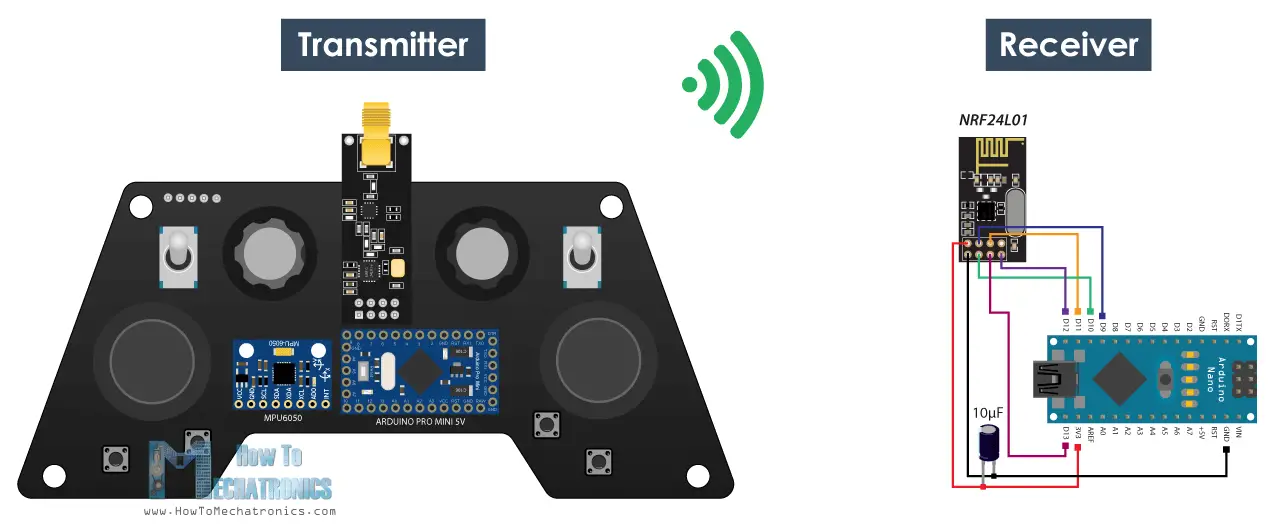
And here’s a simple receiver code where we will receive the data and simply print it on the serial monitor so that we know that the communication works properly. Again we need to include the RF24 library and define the objects and the structure the same way as in the transmitter code. In the setup section when defining the radio communication we need to use the same settings as the transmitter and set the module as receiver using the radio.startListening() function.
/*
    DIY Arduino based RC Transmitter Project
              == Receiver Code ==

  by Dejan Nedelkovski, www.HowToMechatronics.com
  Library: TMRh20/RF24, https://github.com/tmrh20/RF24/
*/
#include <SPI.h>
#include <nRF24L01.h>
#include <RF24.h>
RF24 radio(10, 9);   // nRF24L01 (CE, CSN)
const byte address[6] = "00001";

unsigned long lastReceiveTime = 0;
unsigned long currentTime = 0;

// Max size of this struct is 32 bytes - NRF24L01 buffer limit
struct Data_Package {
  byte j1PotX;
  byte j1PotY;
  byte j1Button;
  byte j2PotX;
  byte j2PotY;
  byte j2Button;
  byte pot1;
  byte pot2;
  byte tSwitch1;
  byte tSwitch2;
  byte button1;
  byte button2;
  byte button3;
  byte button4;
};

Data_Package data; //Create a variable with the above structure

void setup() {
  Serial.begin(9600);
  radio.begin();
  radio.openReadingPipe(0, address);
  radio.setAutoAck(false);
  radio.setDataRate(RF24_250KBPS);
  radio.setPALevel(RF24_PA_LOW);
  radio.startListening(); //  Set the module as receiver
  resetData();
}
void loop() {
  // Check whether there is data to be received
  if (radio.available()) {
    radio.read(&data, sizeof(Data_Package)); // Read the whole data and store it into the 'data' structure
    lastReceiveTime = millis(); // At this moment we have received the data
  }
  // Check whether we keep receving data, or we have a connection between the two modules
  currentTime = millis();
  if ( currentTime - lastReceiveTime > 1000 ) { // If current time is more then 1 second since we have recived the last data, that means we have lost connection
    resetData(); // If connection is lost, reset the data. It prevents unwanted behavior, for example if a drone has a throttle up and we lose connection, it can keep flying unless we reset the values
  }
  // Print the data in the Serial Monitor
  Serial.print("j1PotX: ");
  Serial.print(data.j1PotX);
  Serial.print("; j1PotY: ");
  Serial.print(data.j1PotY);
  Serial.print("; button1: ");
  Serial.print(data.button1);
  Serial.print("; j2PotX: ");
  Serial.println(data.j2PotX);
}

void resetData() {
  // Reset the values when there is no radio connection - Set initial default values
  data.j1PotX = 127;
  data.j1PotY = 127;
  data.j2PotX = 127;
  data.j2PotY = 127;
  data.j1Button = 1;
  data.j2Button = 1;
  data.pot1 = 1;
  data.pot2 = 1;
  data.tSwitch1 = 1;
  data.tSwitch2 = 1;
  data.button1 = 1;
  data.button2 = 1;
  data.button3 = 1;
  data.button4 = 1;
}Code language: Arduino (arduino)
In the main loop using the available() function we check whether there is an incoming data. If true we simply read the data and store it into the variables of the structure. Now we can print the data on the serial monitor to check whether the transmission work properly. Also using the millis() function and an if statement we check whether we keep receiving data, or if we don’t receive data for a period longer than 1 second, then we reset variables to their default values. We use this to prevent unwanted behavior, for example if a drone has a throttle up and we lose connection it can keep flying away unless we reset the values.
So that’s it. Now we can implement this method of receiving the data for any Arduino project. For example here the code for controlling the Arduino robot car from one of my previous videos.
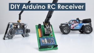
As an update to this project, I made a dedicated Arduino based RC Receiver. Again, it’s based on the Arduino Pro mini board and it has several ready to use servos and ESCs connections, placed on a compact PCB.
Arduino Robot Car Wireless Control using RC Transmitter
Arduino Code:
Here we need to define the libraries, the structure and the radio communication as explained earlier. Then in the main loop we just need read the incoming data and use any of it for whatever we want. In this case I use the joystick 1 values for driving the car.
Arduino Ant Robot / Hexapod control using Arduino RC Transmitter
Arduino Code:
In the exact same way I made the Arduino Ant Robot from my previous video to be wirelessly controlled using this Arduino RC Transmitter. We just need to read the data, and according to it execute the appropriate functions, like moving forward, left, right, bite, attack and so on.
ESC and Servo Control using RC Transmitter
Lastly, let’s take a look how can this transmitter be used for controlling commercial RC devices.
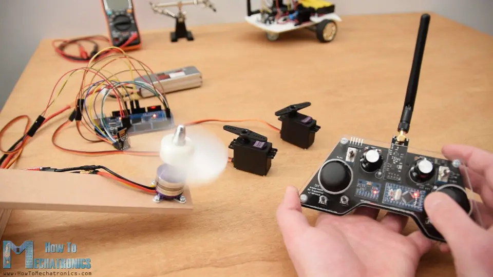
Usually for these devices we need to control their servos or brushless motors. So after receiving the data from the transmitter, for controlling servo we simply use the Arduino Servo library and use values from 0 to 180 degrees. For controlling brushless motor using ESC, we can again use the servo library for generating the 50Hz PWM signal used for controlling the ESC. By varying the duty cycle from 1000 to 2000 microseconds we control the RPM of the motor from zero to maximum. However, more on controlling brushless motors using ESC in my next tutorial.
See Also
Arduino RC Airplane | 100% DIY
Please note that we actually cannot bind the standard RC receiver system with this NRF24L01 2.4GHz system. Instead, we need to modify or create our own receiver consisting of an Arduino and NRF24L01 Module. From there we can than generate the appropriate PWM or PPM signals for controlling the RC device.
/*
    DIY Arduino based RC Transmitter Project
   == Receiver Code - ESC and Servo Control ==

  by Dejan Nedelkovski, www.HowToMechatronics.com
  Library: TMRh20/RF24, https://github.com/tmrh20/RF24/
*/
#include <SPI.h>
#include <nRF24L01.h>
#include <RF24.h>
#include <Servo.h>

RF24 radio(10, 9);   // nRF24L01 (CE, CSN)
const byte address[6] = "00001";

unsigned long lastReceiveTime = 0;
unsigned long currentTime = 0;

Servo esc;  // create servo object to control the ESC
Servo servo1;
Servo servo2;
int escValue, servo1Value, servo2Value;

// Max size of this struct is 32 bytes - NRF24L01 buffer limit
struct Data_Package {
  byte j1PotX;
  byte j1PotY;
  byte j1Button;
  byte j2PotX;
  byte j2PotY;
  byte j2Button;
  byte pot1;
  byte pot2;
  byte tSwitch1;
  byte tSwitch2;
  byte button1;
  byte button2;
  byte button3;
  byte button4;
};

Data_Package data; //Create a variable with the above structure

void setup() {
  Serial.begin(9600);
  radio.begin();
  radio.openReadingPipe(0, address);
  radio.setAutoAck(false);
  radio.setDataRate(RF24_250KBPS);
  radio.setPALevel(RF24_PA_LOW);
  radio.startListening(); //  Set the module as receiver
  resetData();
  esc.attach(9);
  servo1.attach(3);
  servo2.attach(4);
}
void loop() {
  // Check whether we keep receving data, or we have a connection between the two modules
  currentTime = millis();
  if ( currentTime - lastReceiveTime > 1000 ) { // If current time is more then 1 second since we have recived the last data, that means we have lost connection
    resetData(); // If connection is lost, reset the data. It prevents unwanted behavior, for example if a drone jas a throttle up, if we lose connection it can keep flying away if we dont reset the function
  }
  // Check whether there is data to be received
  if (radio.available()) {
    radio.read(&data, sizeof(Data_Package)); // Read the whole data and store it into the 'data' structure
    lastReceiveTime = millis(); // At this moment we have received the data
  }
  // Controlling servos
  servo1Value = map(data.j2PotX, 0, 255, 0, 180);
  servo2Value = map(data.j2PotY, 0, 255, 0, 180);
  servo1.write(servo1Value);
  servo2.write(servo2Value);
  // Controlling brushless motor with ESC
  escValue = map(data.pot1, 0, 255, 1000, 2000); // Map the receiving value form 0 to 255 to 0 1000 to 2000, values used for controlling ESCs
  esc.writeMicroseconds(escValue); // Send the PWM control singal to the ESC
}

void resetData() {
  // Reset the values when there is no radio connection - Set initial default values
  data.j1PotX = 127;
  data.j1PotY = 127;
  data.j2PotX = 127;
  data.j2PotY = 127;
  data.j1Button = 1;
  data.j2Button = 1;
  data.pot1 = 1;
  data.pot2 = 1;
  data.tSwitch1 = 1;
  data.tSwitch2 = 1;
  data.button1 = 1;
  data.button2 = 1;
  data.button3 = 1;
  data.button4 = 1;
}Code language: Arduino (arduino)
So that’s it. I hope you enjoyed this video and learned something new. Feel free to ask any question in the comments section below and check my Arduino Projects Collection.
Hello Mr. Dejan. I’m an 15 years old high school girl in Turkey and my name is Saliha. I have watced your video of constructing remote control device with Arduino card of pro mini for high school project. Even if I have followed the same steps of you, while loading the codes to the card the system gave the error of “avrdude: stk500_recv(): programmer is not responding” and I failed to upload remote control. Have you seen such an error while creating your card? And if you know the reason of error I would be pleased to get help from you.
Best Regards
Saliha Okur/ TURKEY
Hey Saliha,
try different USB port or different PC to upload the sketch. Make sure you have selected the proper Arduino board and processor as explained in the video. If not working, try to search and find different methods for uploading sketches to an Arduino nano.
Cheers!
3D printer controller.
https://www.thingiverse.com/thing:4674119
That looks great actually. Thanks for the input!
Hi DeJan,
I am going to use the transmitter for RC planes and really do not need the push buttons. I decided I am in more need of trim for aileron, rudder and elevator. So I made B3 and B4 a up and down trim for aileron. If switch 2 is on then B3 and B4 become the trim for the elevator. B1 and B2 are the trim for the rudder. I also have ordered an I2C FRAM to write the results to. I have not added the code for this yet as it will read upon starting and write if you press joystick button 1. I did not need the MPU6050 so that is where I will place the FRAM and make use of the I2C. I also removed some of the throw on the Servos as I do not need the full 180 degree movement. This allowed the trim do not go above or below the limits.
Thanks for your work!
Hey, so glad to hear you found this project interesting. Just to let you know, if you haven’t seen my RC plane video, I mentioned in there that these Joysticks aren’t good at all for controlling planes. Keep that in mind, you need better joysticks for such a purpose for sure.
Hi, I would also like to use the buttons as trim ! Really good idea! If possible, I would be glad if you’d share the code. Thanks a lot
Can you use anything else as a power supply to power this and the other part of this?
Sure, you can use anything which is within the range the Arduino RAW pin can handle, up to 12v.
Greetings Dejan
Can the MPU6050 be deleted, are there any changes in the code?
Thanks for a great project, clear and easy.
You can use the same code without using the MPU6050, but also you could delete that section of the code if you are not using it.
Hi Dejan, could you tell me if it matters what type of batteries I need to use for the transmitter(currently I am using 3.7v 900mah li-ion batteries, they also say TF 14500 on them if that is important), also could you please tell me any troubleshooting ideas for the communication between the transmitter and the receiver, my transmitter looks to be working properly with all the lights coming on, but it will not send any values to the receiver (that is running the test code). Are there any buttons on the transmitter or something that turns it on besides the on/off switch.
Thanks in advance if you can help
Hey, for the batteries the important thing is to be 3.7V x2 = 7.4V. The other parameters are the capacity and it’s not that important.
The main switch powers the Transmitter and it right away puts in transmitting mode. So once you turn the Receiver on as well, the two devices should connect and start communicating. As for what can be wrong, there can be many things. Try to go through all comments you might find a solution. However here are few quick tips: Try to increase the distance a bit between the two devices, try to change the “PALevel” to medium or high on both devices, make sure you use capacitors near the nrf module, double check your connects you can easily mess things with all the wires. If you are using Arduino Mega for the receiver make sure you connect the nrf module to the right SPI pins on the Mega which are on other pins compared to the Uno and Nano board.
I hope you will get your project working with some of these tips. Cheers!
Hey Dejan your rc project is awsome. i wonder if it is easy too apply the project too
an arduino mega 2560, so it could bee fitted with a monster amount of channels.
both for the reciever and the transmitter.
Thanks! Well the working principle and the code would be the same. You just need to connect the NRF24L01 module to the appropriate SPI pins of the MEGA board and that’s it.
Thanks for te reply i will try that
Yeah, this is a great project, well explained, however, like some other PCB based projects I’ve encountered it is very important to give the ONE source for the component used. In other words, take the Arduino Pro Mini, you listed 3 sources for
the device but only the EBAY version is compatible with your PCB. The pinout of the other two are not compatible (I ordered the one from Amazon) and was frustrated to discover the incompatibility. There is no point listing Amazon and Banggood if their pinout is not right. Now I wait 2 months for the Ebay part to come…
Hey, I’m sorry to hear that. I’ve just updated the post to be a bit more clear about the different version of the Arduino boards. So now there are 3 versions of the PCB. The first one is the same as shown in the video, V2 is compatible with the Arduino boards which are more accessable and easy to find, and V3 is with AMS1117 3.3V voltage regulator instead of the HT7333, because people often times have hard time finding this regulator.
I hope the instructions are fine now so everyone can choose the right version of the PCB.
Thank you for this great project, and hoping you may be able to assist me. What alternative regulator can i use, instead of the HT7333? I have received the PCB, but am having some challenges getting the HT7333.
Hey, thanks! Well the AMS1117 3.3v is very similar to this voltage regulator, but still the pins are different location, you cannot solder on the same pads. Only the GND is on same location, the Vin and Vout should be swapped. Maybe, for example, you could use the AMS1117, move it a bit away from the pads, and connect the appropriate pads to the PCB with wires, GND to GND, Vin to Vin, and Vout to Vout.
Hey, I am making this board but i accidentally got a Arduino pro mini 3.3v instead of the Arduino pro mini 5v. I am wondering if the Arduino pro mini 3.3v would work fine or if I can tweak anything to make it work.(also, I had to redesign the PCB so this Arduino pro mini 3.3v could fit, now I cant find a Arduino pro mini that is 5v that will get to me in time with the same pin layout)
I would love if someone could help, thanks in advance
Hey, you should be able to use the 3.3V version of Arduino Pro Mini. You don’t need anything to change. The power input will go to Vin, the Arduino has a voltage regulator which will drop the incoming voltage from the battery to 3.3V. The NRF24L01 module works on 3.3V anyway, so you have no problem with it. The joysticks and the buttons will work without a problem as well. I haven’t tested all of this but I think you are good to go.
Let us know whether it worked.
I am pretty sure that the 3.3v one would work but I am having a lot of problems with the board communicating with my computer, I normally get problems like this but I fix it by changing what processor my computer is looking for. Sadly this did not work this time because I don’t understand much about uploading code through the USB to serial UART interface. I ended up finding the 5v board with the right pin layout.
Anyways, I love your channel so much and I really like how you still answer questions even on projects that are over a year old. Thanks.
Well I’m trying to do my best. Thank you, cheers!
I have been following this website for a while and now I’m an active member :). I have followed this tutorial to a T but I cannot get the NRF24L01+ to communicate even the example sketch. I’ve soldered it to the board and I can verify continuity between it and the Arduino pro mini. What could I be doing wrong?
Hey, glad to hear it. Please provide a bit more information for your case. So you have the PCB of this Arduino RC Transmitter and you cannot get it working? Make sure you are using all the right components, 3.3v provided to the nRF modules from dedicated power sources and using a decouple capacitors to them. Try to read the comments on this post as well as the comments on the dedicated NRF24L01 tutorial.
I have been through the comments multiple times. I am doing it again but this time I am not soldering anything to the board besides pins to connect jumper wires. I have the NRF24L01+ Breakout Adapter so I plan to bypass the capacitors and voltage regulator parts at least for this build. I also am going to use a nano because I have plenty of those lying around.
hi,
i think i am facing the same issue. it looks like the communication between the transmitter and the receiver is not working. i ordered the pcb for the transmitter and checked everything twice. the transmitter reads the joysticks and buttons. the receiver is running the code to show the serial output. it gives me only the following initial values as my serial output “j1PotX: 127; j1PotY: 127; button1: 1; j2PotX: 127”.
questions:
1. will it be okay to run the arduino nano connected to a usb power suppliy or will it limit the 3.3 volt output an let the NRF24L01 fail?
2. would it possible that the libaries for the NRF24L01 have been changed and cause the communication to fail?
thanks for your support and thanks for sharing your work!
regards
michael
Hey, powering the Arduino nano through the USB port is fine, but the problem is the 3.3v output which might not be power enough for the NRF24L01 module. Therefore, it’s recommended the power to come from a different power source, for example from a battery and then using a voltage divider dropped to 3.3v. Sometimes the nRF module can work with just the 3.3v output but sometimes it doesn’t. Also make sure you use a capacitor right next to it in order the power to be more stable.
Hi, i was facing the same issue with my remote. But after some debugging in managed to get things running.
1. in both sketches (receiver and transmitter) in changed “radio.setPALevel(RF24_PA_LOW);” to “radio.setPALevel(RF24_PA_MIN);” MIN ist the lowest output level of -18dBm, LOW equals -12dBm.
2. in the transmitter sketch i added “radio.stopListening();” after the coding “radio.setPALevel(RF24_PA_MIN);”
3. uncommented the coding “radio.setDataRate(RF24_250KBPS);” because the transmission data rate setting RF24_250KBPS will fail for non-plus units. I am using the NRF24L01+PA+LNA modul as the transmitter and NRF24L01 as the receiver. i had to uncomment “radio.setDataRate(RF24_250KBPS);” in both sketches. Uncommenting only in the receiver sketch was not successfull.
…will need to to some more testing…
These are good tips, thanks for the input!
Congratulations for this masterpiece.
you really helped me and everyone o search on google for ” Arduino Rc Transmitter”
I’m using your idea of creating a package of data to send it all at once its the first and only example of something like this I am really happy with the result of yout transmitter I hope mine turns as well as yours.
I will keep you posted.
Tell me, what software did you use to crate that circuit diagram?
And… a very important question:
If you do it again now from scratch what changes you would make to it???
For now Best regards, directly from Portugal.
Keep up with the good work!
Thank you! I’m using Illustrator for the circuits.
If I do this project from scratch again I would add few LEDs. They would be useful for getting feedback info from the controlled object, like for example to we can track the battery status and turn on a LED on the receiver when the battery will be low.
Also maybe change the joysticks, as they are not really good, they have small movement range and kind of bad response. For example, if you see my Arduino RC Airplane video you can see that it’s a bit hard to control it with this Transmitter. But changing the joysticks would be mean totally different design because the joysticks that are good are much bigger, like 3 times bigger and wouldn’t fit like that on a PCB design.
Hi, i try to use an arduino nano, but it doesn’ t work in the breadboard. Can the arduino nano be the problem?
Hey, it should work just fine with the Arduino Nano board, even can work even with Mega and UNO, as long as all connections are correct. Try the simpler examples from the NRF24L01 tutorial to make sure you connect the modules correct.
Hello Dejan!
Great, Great Project! I got the remote control done just yesterday!
But I’m with problems with communicating with the Arduino Uno — I’m using the ICSP header of Uno to connect the nrf24 transceiver, but no success. I noticed in a schemmatic you joined in this project, that you don’t use the ICSP, but digital pins.
What can be the problem here?
Kind Regards!
P.S. — I’m using an Arduino Motor Shield R3 on top of the Uno board.
Maybe I got to write code for the SPI library? Trying to figure out what’s happening…
Hello Dejan,
I come from Germany and came across your projects via You Tube.
For me this is the best site I have found so far.
I want to recreate the project with the Arduino RC transmitter, I ordered the JLCBCB boards with your help (gerber file).
I am eagerly awaiting your next project for the recipient.
I think it’s great that there are people like you who make their knowledge available to others, thank you …..
Many greetings from Germany
Wolfgang Rupp
PS. Sorry for my bad english
Thank you, I’m glad to hear this!
Hi Howtomechatronics,
For school I have to make a remote control car with arduino. I decided to use an NRF24L01 module for communication between the car and the remote control. But the problem is that the two modules cannot communicate with each other if I power the two modules with 9V batteries (The boards are well on but nothing is happening). Every time, the receiver must be connected via USB to the PC. I use the same code as in your explanation of the NRD24L01 module. Could you help me please?
thank you
Hey, the NRF24L01 module operates at 3.3V. You can power the module through 3.3V pin of the Arduino, though sometimes that could cause problems and the connection might fail because the Arduino 3.3V cannot provide enough current for the module. Therefore, it’s good idea to power the NRF24L01 module with separate 3.3V power supple, which can come from a voltage regulator in case you are using 9V battery as you mentioned. You can use the AMS1117 voltage regulator which will convert the 9V to 3.3V. Also you should use a decoupling capacitor right next to the module to smooth the power input. Also try the other simpler examples from my Arduino NRF24l01 tutorial to get modules working.
Hello, this is a great project. I had earlier thought of purchasing a commercial transmitter-receiver set but I have now changed my mind to do it myself. One question though, is it possible to send characters or a string message using this transmitter module?
Hey, thanks! Sure, you can modify the code and send characters and strings messages. Have fun building!
Hi, great project! I’m trying to build it myself but I’m having some trouble with the NRF24l01 module. There is no communication when I’m using the module with external antenna. The modules without external antenna are working fine (also the tutorial on wireless communication), but when I replace one of the modules for a module with external antenna the communication stops..I have tried shielding the module, placed capacitors etc. but nothing works. Do you have any suggestions?
thanks for the help!
Hey, thanks! It sounds like the module with the antenna might be a faulty one, or it’s a bit different model/version. I’m not quite sure what I could suggest to try, as you’ve already managed to get the wireless communication working with the other modules. Maybe try to set the two modules when trying to communicate at a greater distance.
Thanks for this masterpiece !
you expained every thing better than anyone here
but one thing i cant understand is how am i gonna connect my servos and ESCs i mean in receiver what is channel 1 there are only 2 connections responding to each channel in your diagram while there should be 3
i wanna connect 4 servos and 2 BLDCs where would i connect them
I am making this remote controller and there is problem in the gerber file i guess because when i try to code the transmitter there is error “programmer is not reaponding” and also arduino pro mini doesnt power up. i tried to simply connect it with cell but it didnt light up. please help i am frustrated.
Hey, thanks! So, once you receive all data coming from the Transmitter, you have 14 different variables, each containing data values from the Transmitter. So you can use this data to activate, move or control anything at the receiver side. For driving a servo motor, you just servo.write() function. That’s all explained in the last example, the code at the bottom of the article.
As for the gerber file problem, I don’t think there is one. I’ve just checked it and everything looks fine, plus many people have used it successfully without no issues. That indicates that you have probably made some errors when connecting the components. Maybe a you got a faulty component. Try to trace the input voltage, whether it gets to the RAW pin of the Arduino. I’m not quite sure how can I help you with this problem, you just have to triple check the connections and use multimeter yo check the voltages or the continuity.
P.S. I’m currently working on a new project which will include a dedicated Receiver for this Arduino RC Transmitter and everything you asked will be explained there. It should be ready in a week or two.
Great article Dejan!
Already built a number of versions successfully on breadboard and stripboard.
I have used the Arduino Nano in place of the Pro Mini because of the onboard 3.3v regulator on the Nano being available to power the nRF24L01.
2 doubts
1) Can I use 2 potentiometers instead a joystick ?
2)Is it compulsory to use mpu6050?
Dejan please help me out
Yes, you could use potentiometers instead of the joystick, and the MPU6050 module is optional, you don’t have to include it.
Hey Dejan!
I’ve found your project really interesting and inspiring!
I’m only a high school student and I’m kinda interested in creating an RC airplane model that can fly by it’s own (I mean, not as complex but that has the ability to do a certain flying pattern after pressing one button, like… circles). Should I define the model to every x milliseconds to turn a certain angle so it keeps it´s highness and circling going? Don´t really know how this should be made…
Would really appreciate your help. Keep up with the great work!
Hey, thanks and I’m glad you found this project interesting. To be honest, I don’t have much experience with RC airplanes so I cannot really give you any useful tips at this time.
First off all i want to Thank you for this awesome tutorial i just completed your rc transmitter project for my college work and the great thing is that they are goinig to present it in the event of our college,Thank you very much..i also want to make arduino based drone/quadcopter ,which i can control with your arduino based rc transmitter
Can you help me sir
Hello Dejan,
Thanks for the interesting project that you share with us. I’m 80 years old and still interested in digital projects. I have assembled the hardware, it was very amusing.
Now it’s time to load the software but it doesn’t work, always : “avrdude: stk500_recv(): programmer is not responding – etc…” In the Arduino IDE tools : Board=Arduino Pro Mini, ATmega328P (5V, 16 MHz), port= /dev/cu.usbserial-A93JTGEL, USBasp programmer. My Pro Mini is fabrication RobotDyn. Serial convertor Adapter Module = FT23AL-5V-6 pins. On your project you have only 5 pins ?? When connected to USB, the Pro Mini is working because the preloaded Blink sketch is blinking. Must I cross the RX & TX pins ? The two RX/D1 & TX/D0 jumpers are not placed.
When I connect my FT23RL (6pins) to a separate Pro Mini (6pins) all sketches can be loaded.
What’s wrong with my hardware ?? Can you help me ?
Sorry for my bad English.
Jos
Hey, I’m happy to hear you find this project interesting.
Make sure you have connect the 5 pins correctly. The FTDI DRT pin to Arduino DRT, FTDI TX to Arduino RX, FTDI RX to Arduino TX, VCC to VCC, GND to GND.
Then make sure in the Arduino IDE, under the Tools menu, you select the Arduino Pro or Pro Mini (Tools>Board), then select the correct Processor of your Arduino (Tools>Processor), and finaly select the correct Port yo with you Arduino/FTDI is connect (Tools>Port).
This setup should work. The RX/D1 and TX/D0 jumpers should not be placed.
If you are saying that you can upload sketches on a different Pro Mini, try to connect this Arduino the same way you connect the working one, with 6 pins I guess.
I hope you will be able to solve the problem.
Hello Dejan,
I’m here again. I do my best but I can’t upload any software (f.i. the Blink sketch) because I see always the same error : “The programmer is not responding”. However all connections are the same as another exterior Pro Mini and this one works perfectly. I did all as you suggested, also the good serial port. The 2 jumpers are not placed.
Can you resolve this mysterious problem ?
Jos
The toggle switch you used in the tutorial is 6A 125v on-on 3pin switch but when i went to buy they dont any so they suggested to get 3A 250V on-on switch…will it work ?
Sorry for my bad english
Sure, you can use them.
Hello (again) Dejan,
Although I created the project and works fine with the joysticks, I have problems with the mpu6050. It cannot been scanned on the i2c adresses. The soldering is fine. The arduino pro mini can scan other device on the i2c that i connected to it. Is anything else I must pay attention before changing the mpu6050?
Two things I have to notice:
1. The joysticks are not so sensitive..the change their values quite rapidly
2.The joystick buttons are reversed. you can change them on the code as I did.I also think D0 and D1 are printed wrong on the board but …it doesnt matter
Thanks
Hello Dejan,
Thanks for this project, I am confused with the capacitor C2.
On the diagram one trace comes from ground and the other from the ht7333 output (3.3V)
BUT
on the pcb file and on the real pcb i have on my hands now and testing it
C2 is connected to the ground and on the input of the ht7333 (8V about or 7.4V as you say depending on the batteries).
What is the correct and why?
Please reply.
Thanks in advance
Nick
Hey, that’s a good remark. It’s true, on the circuit diagram the C2 capacitor positive pin is connected to the HT7333 Vout pin and on the PCB to the Vin pin. Actually the recommended setup for the HT7333 is to use two capacitors, one at the Vin pin and the other at the Vout pin. These capacitors are used for stabilizing the voltage output of the HT7333 voltage regulator.
Hi Dejan
Thx so much for sharing this seldom clearly and inspiring documented project, just awesome !
I’m building my own RC controller based on ( and boosted by ) your work and it is going superb thanks to your guidance ! (and google)
I have taken your notes seriously to provide the radio module with a dedicated power source to achieve maximum performance. I assumed it was valid for both TX an RC ends…
So to power the radio modules in my project i use :
– adjustable bucket DC/DC step down converters. on the transmitter side, taking in power from a battery pack consisting of 2 series of 3pcs 18650 batteries in parrallel ( totaling 6 batteries; providing 10.2V 4400mAh) , the arduino board connects trough its barrel jack to this battery pack well whitin the comfort zone of its internal voltage regulation circuitry.
– On the reciever side i opted for dedicated bucket DC/DC convertors for both the arduino board and the radio module because the main power source on that side is a 24V DC power grid ( fed by a 24V DC 800Ah battery pack connected with 140Amp/5kW charger-inverter combo’s, a recipe for fluctuating voltage )
questions
– How come you did NOT use a dedicated power source for the radio module on the reciever end of your project but powered it from the board against your own advice ? I intend to have feedback to the transmitter and my primary power source on the reciever end is unstable, so for maximum redundancy i decided to use dedicated adjustabl bucket DC/DC step down convertors to power my modules on the RC end.
– Is your TX power source autonomy satisfying ? Since the internal voltage circuitry on most 5V Arduino boards require > 6V to insure stability of the board, a 7.2V battery pack’s state of charge would be quickly (?) insufficient for stability ? (thats why i designed a larger/higher voltage battery TX pack) .
For those among us who are just like me, lacking Dejans design and engineering capabilities but still want to engage in Arduino based RC projects, i have a few tips :
– if youre not familiar with crowtail shields and cables google them !! This is prototypers dream material !!! Even a beginner can make projects with this dirt cheap components that would pass a survey and certification for application ! Soldering minimised.
– Mounting, attaching, fixing boards and peripheralis… They have become so small that even M3 screws look monstuous… Holes on a arduino board are only suitable for self-adhesive plastic standoffs because any M3 screw would touch headers and/or circuitry…. peripheral boards often do not even have holes to fix them firmly… I have very satisfying eperience with Tesa powerstrips (google ! ) and hotglue. ( Note on powerstrips : they are VERY powerfull, and availabale in different load capacity versions, they need however SURFACE to hold on to and a arduino board WITH headers has pins sticking out beyond thickness of powerstrips, use common sense and this strips will hold boards to whatever surface with tremedous force)
Thx again Dejan, you helped a lot bringing a much needed RC application here to reality !
Hi Dejan,
Great project, I love it and plan to build it. Onze question, on your parts list you show a link to joysticks without breakout board. If you follow the link, you end up with ps4 joysticks. They will not fit on your pcb. You need PS2 joysticks for that. They are slightly larger. Am I right? Thanks a lot for your help.
Hey, thanks! Well I think you are right. Someone already reported that the links to the joysticks without breakout board don’t fit 100% to the PCB. The problem is that I cannot find links to the correct PS2 joysticks which are without a breakout board. So you could either modify a the PCB (change the joysticks pads) or get the joysticks with the breakout board. However, please note that desoldering the joystick from the breakout board is a bit hard, especially if you don’t have proper desoldering tools.
Wow such awesome detailed tutorial ! Based on your work i can (should be) able to make an application specific RC control for my project.
I’m planning to build one with 5 buttons, 2 pots and a display for feedback and other info like battery soc. Your work makes that a hell of a lot easier for me so a big thank you !!!
Thanks, I’m glad to hear that! Have fun making your own one!
I substituted an AMS1117 for the 3v regulator. Is this a big enough change to make the transmitter not work?
Yeah, you can use the AMS1117 3V regulator instead.
Is it possible to know the value of the two electrolytic capacitors used in this project?
Thank you
They are 10uF, 16V or anything above.
Hello sir! thanks for sharing your project. I want to implement the same project. Please, I wish to ask instead of using Arduino pro mini, can I use Arduino nano in place of it??
Hey, you could use an Arduino Nano, if you connect everything the same, the code would also be the same. However, in this PCB design you can’t use Nano because it has a different footprint compared to the Pro Mini.
Would it be hard to modify the PCB to use the nano?
This is a Great, Great project!!! Thank you very much for sharing it! I’m trying to make it. I ordered all the stuff from the affiliated links, and I got the pcb’s already. It’s a great remote control, fully programmable, I’m looking forward for having it done. Thank You very much for sharing it with us!
Thanks, I’m glad to hear that!
Dear sir
Can I use Arduino nano v3 In place of pro mini
What is the pin Txo and RxI in arduino nano
Can I use same transmitter code without Mpu5060
Please help me sir
Thanking you
Hey, yes, you could use Nano and drop the MPU6050 as well.
Hi Dejan,
your tutorial is really great and i was able to build a transmitter and reciever based on this.
But now i encountered the problem that when i use the reciever with an esc, the system seems to snap from time to time and putting the minmal values for any servo or esc connected.
Have you encountered a similar behavior?
I am quite puzzled about that.
Hey thanks, nice to hear that!
Well no, I haven’t experienced such a problem. You should try to identify what is causing the problem, whether the potentiometers or joysticks, or the wireless communication is messing up the data. Try, using the serial monitor, to track the values at the transmitter, and also at the receiver and you might find out.
Hello Dejan,
I already tried leaving you a comment few times but it doesn’t show so ill try once again.
Great job, I’m in the process of making one transmitter and few receivers but with few modifications (not using arduino board, just atmega328 IC for TX and atmega88 for RX).
I see you used jumpers on TX and RX for programming, but I’m not sure why, lines are not connected to anything until you push the button, so jumpers are not really necessary, it won’t interfere with anything. Or did I get something wrong?
Also I was wondering, is it possible to make some kind of auto bind function? For example, when I turn on the transmitter, it binds to first receiver it finds and ignores all the others? Receivers should have unique addresses and transmitter when turned on should connect to the first one, get his address and then only talk to that one and ignore the others. I tried something, but not sure where to start. Maybe have the same address for all on start in the setup, then connect to first receiver, get his unique ID and change it to that?
Hey Davor,
My point with the jumpers was that, if you use a jumper, connect the line, you would be able to use the Joystick push button which are connected to digital pin 0 and 1. These pins are also the RX and TX pins, and when uploading a sketch to the Arduino, these two pins must be disconnected from anything, otherwise the sketch might fail to be uploaded to the Arduino.
As for you second question, I haven’t experiment with such examples so I couldn’t help you much.
Why at your circuid diogram has 2 decoupling capacitors? (one near NRF24, and second near HT7333)
One is for the NRF24 module, and the other is for the HT7333 module. They both need a decoupling capacitors to work properly.
Really great job. Thank you!! You teach me a lot of wireless connection.
Hope one day I will fly a arduino drone without another receiver through this controller.
Thanks! Sure you will if you love and do DIY projects! 🙂
Hi there,, Thank you for sharing your tutorials to us, specially to newbies on electronics like me 🙂
im just wondering,, your tact switch doen’st have resistors on it,, is it okay to design without it? or i have to put resistors on other side of tact switches? and if ever what values do i have to put? 1k ohms?
and another thing can i add a slide switch for the connection of tx0 and dxi for easy dosconnecting the buttons 🙂
once again thank you very much sir 🙂
Well I didn’t include any resistor for the switches because I’m using the internal pull-up resistors of the Arduino pins. You can see that in the code, when defining the pin modes. As for the tx0 and dxi pins, yeah, you could probably make such a modification.
First of all thank you for making such an interesting thing and may god bless you to make more in future.I also don’t have much knowledge about electronics so my question might be silly.Can i use the arduino board as you have given in the link.The arduino which you’ve given in the link is not same as in the video.won’t there be any problem in using that board.And if yes do we need to left the pin as it is without soldering.Thank you.
Thank you! Well you can notice that there are two links to the Arduino, the one from Ebay is exactly the same as I used in the project.
can i know the value of potentiometer ?
It can be anything from 1K to 100K.
hi im trying to change the arduino you used to the sparkfun pro mini 5v but it doesn’t have the dtr pin for auto reset function will this cause any problems ?
Well it should’t be a problem as long as you have the right FTDI Basic Breakout board to upload the sketch to the Arduino. Other than that, if everything wired as properly it should all work fine.
great job……i like your project
Hi, this is awesome project. We will use it for our uav prototipies. But we have some problems. First we cant find ht7333 🙁 What can we solve that?
And the other problem is as i see you use 2 capacitors. What are they?
We are living in Turkey and we cant find everything here. If you can help us we will be really happy 🙂
Thanx from now..
Hey, thanks! Well you can use different 3.3V voltage regulator, for example the AMS1117. The capacitors are used for stabilizing the input voltage for the NRF24L01 module, they can be anything from 1uF to 100uF.
Can it be used with drone flight controllers?
Yes, but the drone would need an Arduino receiver.
Will it work with both the link for the arduino pro mini you paste ?
Thank you
The one from eBay have the same footprint.
Great project! Thanks for sharing! Can I change MPU50060 to the 0.96″ OLED?
Of course, I have to change sketch, but, as I can see, MPU have same point for connection with arduino
Thanks. Well the MPU6050 uses I2C communication, so you can probably do that if the 0.96″ OLED uses the same I2C communication.
Wow. This is exactly what i was looking for and it flew just into my website visiting.
Great Tutorial. Great details. And funky looking.
So now i will have to weigh my options between a 4 ch rc transmitter and receiver pair from china or this totally funky looking more expensive one, but for me better understable one here, to control and old rc car.
Hello.
First of all thank you for your share. Great Project.
your banggood link for toggle switch refer to 2 pin toggle switch. I think it should be 3 pin? one more thing. I release that we need to remove PCB of joystick, right?
Hey, thanks for the remarks. I’ve just updated the article with the 3 pins toggle switch and also added links to Joystick modules without PCBs. Yes, you are right, in case you have the ones with PCB you will have to desolder them, and I did so. It’s a bit harder to find those without PCB.
Hi – this is exactly what i was looking for. Can you help me this question please?
Which decoupling capacitor can i use?
Thanks for your help, your channel is great!
Thanks! I used 10uF capacitors.
Can we use 100uF capacitor??
Yes, you can use 100uF capacitor.
Looks nice. I’ve been going in the direction of using the ESP8266 and MQTT protocal for my home wireless and network projects. Your Arduino wireless game/everything controller, with just a ESP8266 module replacing the RF module you’re using, looks perfect for my projects too. Thanks for the explosion of ideas your project has had on me 🙂
Thanks, I’m glad to hear this! Have fun making it. 🙂
Dejan, I am interested in your design for controlling rc cars. Couple of questions.
Is there any provision for binding 2.4 gHz standard rc receivers with you system?
Can this be used with brushed motors?
Thanks,
Tony
Hey Tony, we actually cannot bind the two systems, but you will have to make a receiver for the RC car consisting of an Arduino and NRF24L01 module. Then you just have to generate the standard 50Hz PWM signal that controls the servo motors for example or a brushless motor, as explained in the last example. Sure, you can drive brushed motors, for example like I did on the second example, controlling two brushed DC motors using the L298N for driving the robot car. Sorry but I didn’t have a standard RC car so I could demonstrate this method, but it should work.
This is awesome! Do you have any schematic for the Receiver? I’m mainly interested in a general ESC and Servo setup.
Going based on this…
esc.attach(9);
servo1.attach(3);
servo2.attach(4);
Does 9, 3 and 4 refer to Digital Pins D9, D3 and D4? D9 should be pin 13 on the Atmega328 chip, D3 = pin1 and D4 = pin2. Correct?
Thank you! Yes that’s correct, 9, 3 and 4 refer to the digital pins, of course they can be any other digital pins. I updated the article with a schematic for the receiver, check it out. Also I would recommend to check my other detailed tutorial for the NRF24L01 module and the Arduino.
radio.setPALevel(RF24_PA_LOW);
Can I set this to HIGH or MAX to extended range ?
Yes, you can do that. But of course, the module will consume more power that way.
Hello again:)
I’m not a programmer or electronic engineer. I hope this is not a silly question. Wouldn’t we use both “NRF24L01 + PA + LNA” instead of using “NRF24L01” with more/high power on tx side? Doesn’t the coverage of the flat logic be doubled? or more strong/stable?
Is it possible to add oled I2c display
Well yes, it’s possible. The Arduino I2C bus can be used by multiple devices at the same time, the MPU6050 module is currently using but still you should be able to use the OLED display as well.
Hello Dejan, as someone already asked about being able to connect a display to the controller, and yes it is possible, the only question is, how!
I’m a complete newbie, I bought some of the parts needed (waiting for stocks to buy the rest), and this idea of also having a camera mounted on the RC car/drone whatever I will build and a screen on the remote controller sounds really good!
Hoping you will do a follow up video on how to connect a display and actually make it work with a small camera attached to the vehicle.
Thank you for all your great videos, keep it up!
Well, first of all it depends what kind of display you would like to connect and for what purpose. The thing you mentioned, about displaying a camera output attached on a vehicle, I don’t think it’s possible to achieve with this setup and components on the Transmitter. On the other hand, adding a small display for making something like menu system, or reading some simple data coming from the receiver could be implemented, but still it would require a lot of modifications. Not the most simple task, especially if you are new to Arduino.
Thank you for your reply, I should check here more often.
I decided to use an arduino mega with a 3.5″ tft display shield, that leaves me with about 30 digital pins and 6 analog, I connected everything on breadboards so I can upload the code on the mega and test all buttons and the display (for now just simple text, in the future will dig for more info on connecting a camera via the NRF24L01), then if it’s all good, design the PCB and order via JLCPCB.
However, upon further checking your design (which was my inspiration, since I’m 100% newbie), I noticed that you used only 1 pin on your toggle switches, that means your switch is OFF OFF ON, wouldn’t it be better (at least in my case since I use an arduino mega and I got plenty of spare pins) to use 2 pins on the toggle switches? thus making the switch ON OFF ON.
My apologies, I assumed that you use ON OFF ON switch, only now I noticed you use ON ON switches.
I guess in my case I do have to use 2 pins.