In this Arduino Tutorial we will learn what RGB LED is and how to use it with the Arduino Board. You can watch the following video or read the written tutorial below.
What is RGB LED?
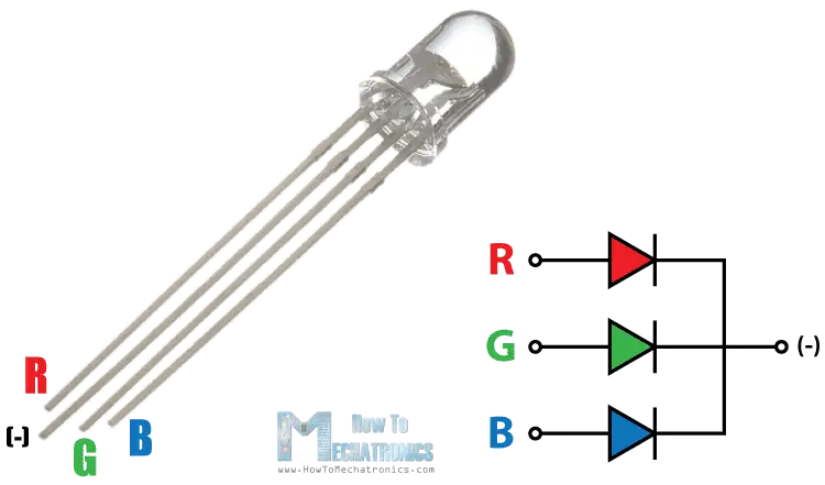
The RGB LED can emit different colors by mixing the 3 basic colors red, green and blue. So it actually consists of 3 separate LEDs red, green and blue packed in a single case. That’s why it has 4 leads, one lead for each of the 3 colors and one common cathode or anode depending of the RGB LED type. In this tutorial I will be using a common cathode one.
Components needed for this tutorial
- RGB LED…………………………………….. Amazon / Bangggod / AliExpress
- 3x 220 Ohms Resistors……………….. Amazon / Banggood / AliExpress
- Arduino Board …………………………… Amazon / Banggood / AliExpress
- Breadboard and Jump Wires ……… Amazon / Banggood / AliExpress
Disclosure: These are affiliate links. As an Amazon Associate I earn from qualifying purchases.
Arduino and RGB LED Circuit Schematics
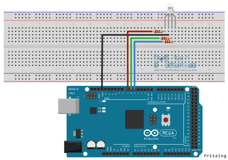
The cathode will be connected to the ground and the 3 anodes will be connected through 220 Ohms resistors to 3 digital pins on the Arduino Board that can provide PWM signal. We will use PWM for simulating analog output which will provide different voltage levels to the LEDs so we can get the desired colors.
We will use PWM for simulating analog output which will provide different voltage levels to the LEDs so we can get the desired colors.
Source Code
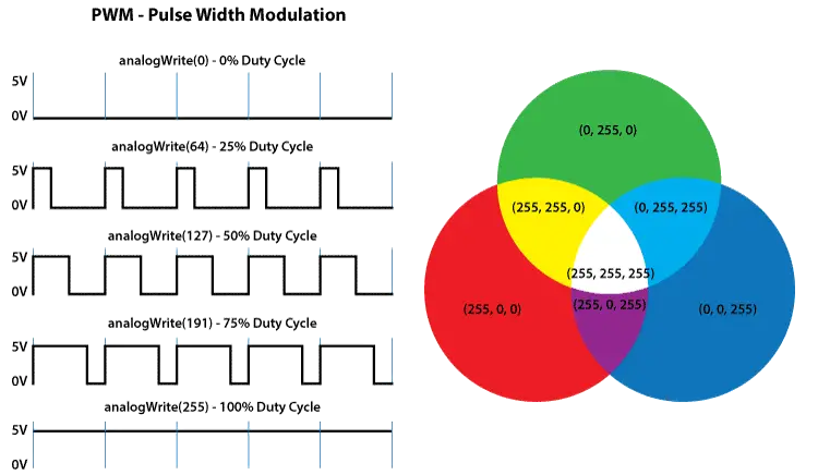
Now let’s see the Arduino sketch. I will use the pins number 7, 6 and 5 and I will name them redPin, greenPin and bluePin. In the setup section we need to define them as outputs. At the bottom of the sketch we have this custom made function named setColor() which takes 3 different arguments redValue, greenValue and blueValue. These arguments represents the brightness of the LEDs or the duty cycle of the PWM signal which is created using the analogWrite() function. These values can vary from 0 to 255 which represents 100 % duty cycle of the PWM signal or maximum LED brightness.
int redPin= 7;
int greenPin = 6;
int bluePin = 5;
void setup() {
pinMode(redPin, OUTPUT);
pinMode(greenPin, OUTPUT);
pinMode(bluePin, OUTPUT);
}
void loop() {
setColor(255, 0, 0); // Red Color
delay(1000);
setColor(0, 255, 0); // Green Color
delay(1000);
setColor(0, 0, 255); // Blue Color
delay(1000);
setColor(255, 255, 255); // White Color
delay(1000);
setColor(170, 0, 255); // Purple Color
delay(1000);
}
void setColor(int redValue, int greenValue, int blueValue) {
analogWrite(redPin, redValue);
analogWrite(greenPin, greenValue);
analogWrite(bluePin, blueValue);
}
Code language: Arduino (arduino)So now in the loop function we will make our program which will change the color of the LED each second. In order to get red light on the LED we will call the setColor() function and set value of 255 for the redValue argument and 0 for the two others. Respectively we can get the two other basic colors, green and blue. For getting other colors we need to mix the arguments values. So for example if set all 3 LEDS to maximum brightness we will get White color and we will get a purple color if we set the following values to the arguments: 170 redValue, 0 greenValue and 255 blueValue. Here’s the demonstration of the sketch.