In this tutorial we will learn how to make wireless communication between two Arduino boards using the nRF24L01 transceiver modules. The nRF24L01 module is very popular choice for wireless communication when using Arduino.
I have already used this module for numerous Arduino projects and you can check out some of them here:
- DIY Arduino RC Transmitter
- Arduino RC Airplane | 100% DIY
- DIY Arduino based RC Hovercraft
- Arduino Wireless Weather Station Project
You can watch the following video or read the written tutorial below. It includes everything we need to know about the nRF24L01 transceiver module, such as the module pinout, working principle, wiring and several code examples.
Overview
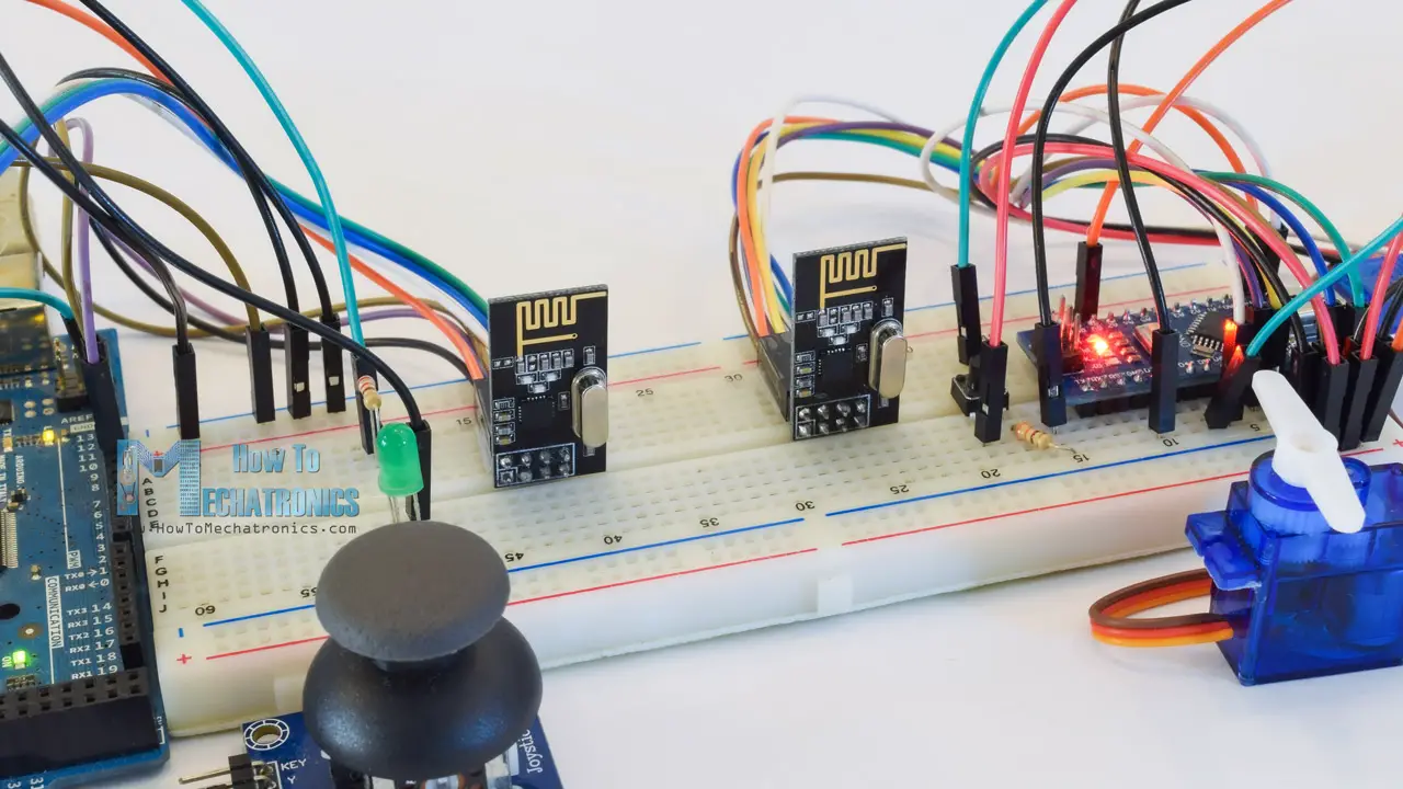
For explaining the wireless communication we will make two examples, the first one will be sending a simple “Hello World” message from one Arduino to another, and in the second example we will have a bi-directional communication between the Arduino boards, where using the Joystick at the first Arduino we will control the servo motor at the second Arduino, and vice versa, using the push button at the second Arduino we will control the LED at the first Arduino.
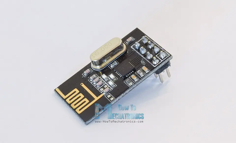
nRF24L01 Transceiver Module
Let’s take a closer look at the NRF24L01 transceiver module. It uses the 2.4 GHz band and it can operate with baud rates from 250 kbps up to 2 Mbps. If used in open space and with lower baud rate its range can reach up to 100 meters.
Here are complete specifications:
| Frequency range | 2.4 – 2.5GHz ISM band |
| Data rates | 250Kbps / 1Mbps / 2Mbps |
| Max. output power | 0dBm |
| Operating voltage | 1.9 – 3.6V |
| Max. operating current | 12.3mA |
| Standby current | 22µA |
| Logic inputs | 5V tolerant |
| Communication range | 100m (open space) |
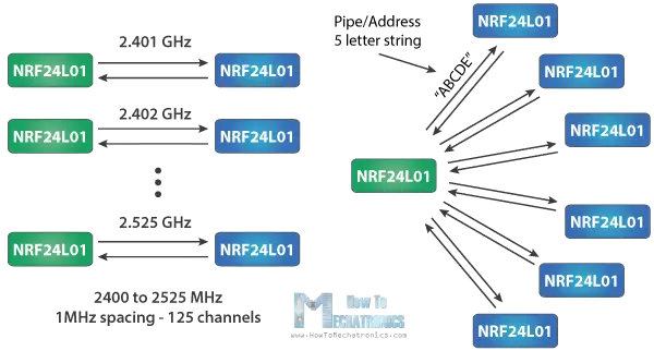
How It Works
The module can use 125 different channels which gives a possibility to have a network of 125 independently working modems in one place. Each channel can have up to 6 addresses, or each unit can communicate with up to 6 other units at the same time.
The power consumption of this module is just around 12mA during transmission, which is even lower than a single LED. The operating voltage of the module is from 1.9 to 3.6V, but the good thing is that the other pins tolerate 5V logic, so we can easily connect it to an Arduino without using any logic level converters.
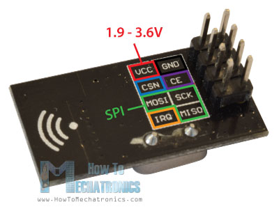
Three of these pins are for the SPI communication and they need to be connected to the SPI pins of the Arduino, but note that each Arduino board has different SPI pins. The pins CSN and CE can be connected to any digital pin of the Arduino board and they are used for setting the module in standby or active mode, as well as for switching between transmit or command mode. The last pin is an interrupt pin which doesn’t have to be used.
Module variations
There are several variations of the NRF24L01 modules. The most popular is the one with on-board antenna. This makes the module to be more compact, but on the other hand, lowers the transmission range to a distance of about 100 meters.
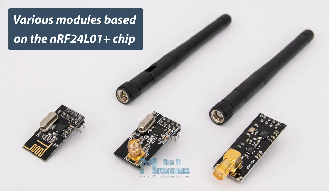
The second variation, instead of on-board antenna, it has a SMA connector and which we can attach a duck antenna for better transmission range.
The third variation shown here, in addition to the duck antenna, it has a RFX2401C chip which includes PA (Power Amplifier) and LNA (Low-Noise Amplifier). This amplifies the NRF24L01 signal and enables even better transmission range of up to 1000 meters in open space.
nRF24L01 Module Pinout
Here’s a detailed look at the NRF24L01 pinout, as well as the NRF24L01+ PA/LNA module.
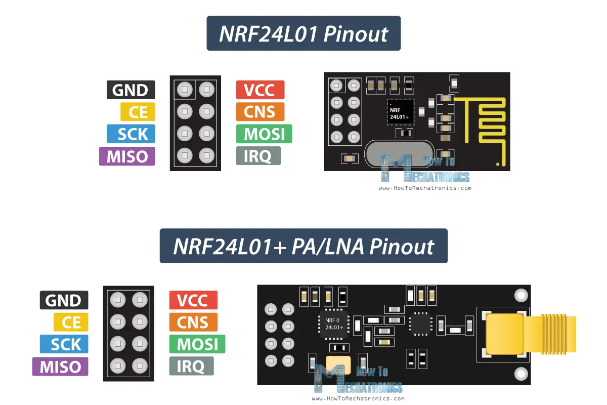
Both modules, the NRF24L01 and the NRF24L01+ PA/LNA have the same pinout, so we can connect them in our circuit the same way.
How to Connect the nRF24L01 to Arduino
Here’s how we need to connect the NRF24L01 modules to the Arduino boards.
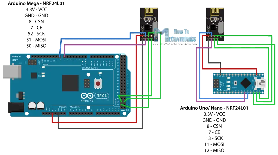
As I already mentioned, each Arduino board has different SPI pins, so keep that in mind when connecting the modules to your Arduino board.
| Arduino | SCK | MISO | MOSI | SS |
| Uno | 13 | 12 | 11 | 10 |
| Nano | 13 | 12 | 11 | 10 |
| Mega | 52 | 50 | 51 | 53 |
You can get the components needed for this Arduino tutorial from the links below:
- NRF24L01 Transceiver Module……… Amazon / Banggood / Aliexpress
- Arduino Board ……………………………… Amazon / Banggood / Aliexpress
- Breadboard and Jump Wires ………… Amazon / Banggood / Aliexpress
Disclosure: These are affiliate links. As an Amazon Associate I earn from qualifying purchases.
Arduino and nRF24L01 Code
Once we connect the NRF24L01 modules to the Arduino boards we are ready to make the codes for both the transmitter and the receiver.
First we need to download and install the RF24 library which makes the programming less difficult. We can also install this library directly from the Arduino IDE Library Manager. Just search for “rf24” and find and install the one by “TMRh20, Avamander”.
Here are the two codes for the wireless communication and below is the description of them.
Transmitter Code
/*
* Arduino Wireless Communication Tutorial
* Example 1 - Transmitter Code
*
* by Dejan Nedelkovski, www.HowToMechatronics.com
*
* Library: TMRh20/RF24, https://github.com/tmrh20/RF24/
*/
#include <SPI.h>
#include <nRF24L01.h>
#include <RF24.h>
RF24 radio(7, 8); // CE, CSN
const byte address[6] = "00001";
void setup() {
radio.begin();
radio.openWritingPipe(address);
radio.setPALevel(RF24_PA_MIN);
radio.stopListening();
}
void loop() {
const char text[] = "Hello World";
radio.write(&text, sizeof(text));
delay(1000);
}Code language: Arduino (arduino)Receiver Code
/*
* Arduino Wireless Communication Tutorial
*       Example 1 - Receiver Code
*
* by Dejan Nedelkovski, www.HowToMechatronics.com
*
* Library: TMRh20/RF24, https://github.com/tmrh20/RF24/
*/

#include <SPI.h>
#include <nRF24L01.h>
#include <RF24.h>

RF24 radio(7, 8); // CE, CSN

const byte address[6] = "00001";

void setup() {
  Serial.begin(9600);
  radio.begin();
  radio.openReadingPipe(0, address);
  radio.setPALevel(RF24_PA_MIN);
  radio.startListening();
}

void loop() {
  if (radio.available()) {
    char text[32] = "";
    radio.read(&text, sizeof(text));
    Serial.println(text);
  }
}Code language: Arduino (arduino)
Code Description
So we need to include the basic SPI and the newly installed RF24 libraries and create an RF24 object. The two arguments here are the CSN and CE pins.
RF24 radio(7, 8); // CE, CSNCode language: Arduino (arduino)Next we need to create a byte array which will represent the address, or the so called pipe through which the two modules will communicate.
const byte address[6] = "00001";Code language: Arduino (arduino)We can change the value of this address to any 5 letter string and this enables to choose to which receiver we will talk, so in our case we will have the same address at both the receiver and the transmitter.
In the setup section we need to initialize the radio object and using the radio.openWritingPipe() function we set the address of the receiver to which we will send data, the 5 letter string we previously set.
radio.openWritingPipe(address);Code language: Arduino (arduino)On the other side, at the receiver, using the radio.setReadingPipe() function we set the same address and in that way we enable the communication between the two modules.
radio.openReadingPipe(0, address);Code language: Arduino (arduino)Then using the radio.setPALevel() function we set the Power Amplifier level, in our case I will set it to minimum as my modules are very close to each other.
radio.setPALevel(RF24_PA_MIN);Code language: Arduino (arduino)Note that if using a higher level it is recommended to use a bypass capacitors across GND and 3.3V of the modules so that they have more stable voltage while operating.
Next we have the radio.stopListening() function which sets module as transmitter, and on the other side, we have the radio.startListening() function which sets the module as receiver.
// at the Transmitter
radio.stopListening();Code language: Arduino (arduino)
// at the Receiver
radio.startListening();Code language: Arduino (arduino)In the loop section, at the transmitter, we create an array of characters to which we assign the message “Hello World”. Using the radio.write() function we will send that message to the receiver. The first argument here is the variable that we want to be sent.
void loop() {
 const char text[] = "Hello World";
 radio.write(&text, sizeof(text));
 delay(1000);
}Code language: Arduino (arduino)
By using the “&” before the variable name we actually set an indicating of the variable that stores the data that we want to be sent and using the second argument we set the number of bytes that we want to take from that variable. In this case the sizeof() function gets all bytes of the strings “text”. At the end of the program we will add 1 second delay.
Using the radio.write() function we can send maximum of 32 bytes at a time.
On the other side, at the receiver, in the loop section using the radio.available() function we check whether there is data to be received. If that’s true, first we create an array of 32 elements, called “text”, in which we will save the incoming data.
void loop() {
  if (radio.available()) {
    char text[32] = "";
    radio.read(&text, sizeof(text));
    Serial.println(text);
  }
}Code language: Arduino (arduino)
Using the radion.read() function we read and store the data into the “text” variable. At the end we just print text on the serial monitor. So once we upload both programs, we can run the serial monitor at the receiver and we will notice the message “Hello World” gets printed each second.
Troubleshooting
It’s worth noting that power supply noise is one of the most common issues people experience when trying to make successful communication with the NRF24L01 modules. Generally, RF circuits or radio frequency signals are sensitive to power supply noise. Therefore, it’s always a good idea to include a decoupling capacitor across the power supply line. The capacitor can be anything from 10uF to 100uF.
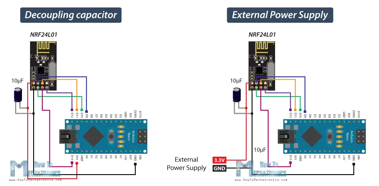
Another common issue is that the 3.3V pin of the Arduino boards, cannot always supply enough power to the NRF24L01 module. So, powering the module with an external power source is also a good idea.
Bi-directional Wireless Communication with two NRF24L01 and Arduino
Let’s see the second example, a bi-directional wireless communication between two Arduino boards. Here’s the circuit schematics:
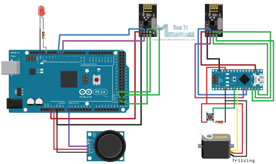
You can get the components needed for this example from the links below:
- NRF24L01 Transceiver Module………… Amazon / Banggood / AliExpress
- Arduino Board…………………………………. Amazon / Banggood / AliExpress
- Joystick Module ………………………………. Amazon / Banggood / AliExpress
- Servo Motor ……………………………………. Amazon / Banggood / AliExpress
- Pushbutton …………………………………….. Amazon / Banggood / AliExpress
- LED ………………………………………………… Amazon / Banggood / AliExpress
Disclosure: These are affiliate links. As an Amazon Associate I earn from qualifying purchases.
nRF24L01 Source Code
Here are the two codes and their description below.
Transmitter Code
/*
* Arduino Wireless Communication Tutorial
*     Example 2 - Transmitter Code
*
* by Dejan Nedelkovski, www.HowToMechatronics.com
*
* Library: TMRh20/RF24, https://github.com/tmrh20/RF24/
*/

#include <SPI.h>
#include <nRF24L01.h>
#include <RF24.h>

#define led 12

RF24 radio(7, 8); // CE, CSN
const byte addresses[][6] = {"00001", "00002"};
boolean buttonState = 0;

void setup() {
  pinMode(12, OUTPUT);
  radio.begin();
  radio.openWritingPipe(addresses[1]); // 00002
  radio.openReadingPipe(1, addresses[0]); // 00001
  radio.setPALevel(RF24_PA_MIN);
}

void loop() {
  delay(5);

  radio.stopListening();
  int potValue = analogRead(A0);
  int angleValue = map(potValue, 0, 1023, 0, 180);
  radio.write(&angleValue, sizeof(angleValue));

  delay(5);
  radio.startListening();
  while (!radio.available());
  radio.read(&buttonState, sizeof(buttonState));
  if (buttonState == HIGH) {
    digitalWrite(led, HIGH);
  }
  else {
    digitalWrite(led, LOW);
  }
}Code language: Arduino (arduino)
Receiver Code
/*
* Arduino Wireless Communication Tutorial
*     Example 2 - Receiver Code
*
* by Dejan Nedelkovski, www.HowToMechatronics.com
*
* Library: TMRh20/RF24, https://github.com/tmrh20/RF24/
*/

#include <SPI.h>
#include <nRF24L01.h>
#include <RF24.h>
#include <Servo.h>

#define button 4

RF24 radio(7, 8); // CE, CSN
const byte addresses[][6] = {"00001", "00002"};
Servo myServo;
boolean buttonState = 0;

void setup() {
  pinMode(button, INPUT);
  myServo.attach(5);
  radio.begin();
  radio.openWritingPipe(addresses[0]); // 00001
  radio.openReadingPipe(1, addresses[1]); // 00002
  radio.setPALevel(RF24_PA_MIN);
}

void loop() {
  delay(5);
  radio.startListening();
  if ( radio.available()) {
    while (radio.available()) {
      int angleV = 0;
      radio.read(&angleV, sizeof(angleV));
      myServo.write(angleV);
    }
    delay(5);
    radio.stopListening();
    buttonState = digitalRead(button);
    radio.write(&buttonState, sizeof(buttonState));
  }
}Code language: Arduino (arduino)
What’s different here from the previous example is that we need to create two pipes or addresses for the bi-directional communication.
const byte addresses[][6] = {"00001", "00002"};Code language: Arduino (arduino)In the setup section we need to define both pipes, and note that the writing address at the first Arduino needs to be the reading address at the second Arduino, and vice versa, the reading address at the first Arduino needs to be the writing address at the second Arduino.
// at the Transmitter
radio.openWritingPipe(addresses[1]); // 00001
radio.openReadingPipe(1, addresses[0]); // 00002Code language: Arduino (arduino)
// at the Receiver
radio.openWritingPipe(addresses[0]); // 00002
radio.openReadingPipe(1, addresses[1]); // 00001Code language: Arduino (arduino)In the loop section using the radio.stopListening() function we set the first Arduino as transmitter, read and map the value of Joystick from 0 to 180, and using the radio.write() function send the data to the receiver.
radio.stopListening();
int potValue = analogRead(A0);
int angleValue = map(potValue, 0, 1023, 0, 180);
radio.write(&angleValue, sizeof(angleValue));Code language: Arduino (arduino)
On the other side, using the radio.startListening() function we set the second Arduino as receiver and we check whether there is available data. While there is data available we will read it, save it to the “angleV” variable and then use that value to rotate the servo motor.
radio.startListening();
  if ( radio.available()) {
    while (radio.available()) {
      int angleV = 0;
      radio.read(&angleV, sizeof(angleV));
      myServo.write(angleV);
    }Code language: Arduino (arduino)
Next, at the transmitter, we set the first Arduino as receiver and with an empty “while” loop we wait for the second Arduino the send data, and that’s the data for the state of the push button whether is pressed or not. If the button is pressed the LED will light up. So these process constantly repeats and both Arduino boards are constantly sending and receiving data.
Example 3 – Sending multiple variables in a single package
Let’s take a look at one more example code using the NRF24L01 modules. Everything remains the same as in the previous examples, expect for the way we structure and send the date.
Transmitter Code
/*
  Arduino Wireless Communication Tutorial
      Example 1 - Transmitter Code

  by Dejan Nedelkovski, www.HowToMechatronics.com

  Library: TMRh20/RF24, https://github.com/tmrh20/RF24/
*/

#include <SPI.h>
#include <nRF24L01.h>
#include <RF24.h>

RF24 radio(7, 8); // CE, CSN

const byte address[6] = "00001";

// Max size of this struct is 32 bytes - NRF24L01 buffer limit
struct Data_Package {
  byte a = 0;
  byte b = 125;
  byte c = 255;
  int d = 1024;
  float e = 3.141592;
  String f = "Test";
};

Data_Package data; // Create a variable with the above structure

void setup() {
  radio.begin();
  radio.openWritingPipe(address);
  radio.setPALevel(RF24_PA_MIN);
  radio.stopListening();
}

void loop() {
  // Send the whole data from the structure to the receiver
  radio.write(&data, sizeof(Data_Package));
  delay(500);
}Code language: Arduino (arduino)
So, we can create a struct which is actually a collection of various types of variables.
// Max size of this struct is 32 bytes - NRF24L01 buffer limit
struct Data_Package {
byte a = 0;
byte b = 125;
byte c = 255;
int d = 1024;
float e = 3.141592;
String f = "Test";
};
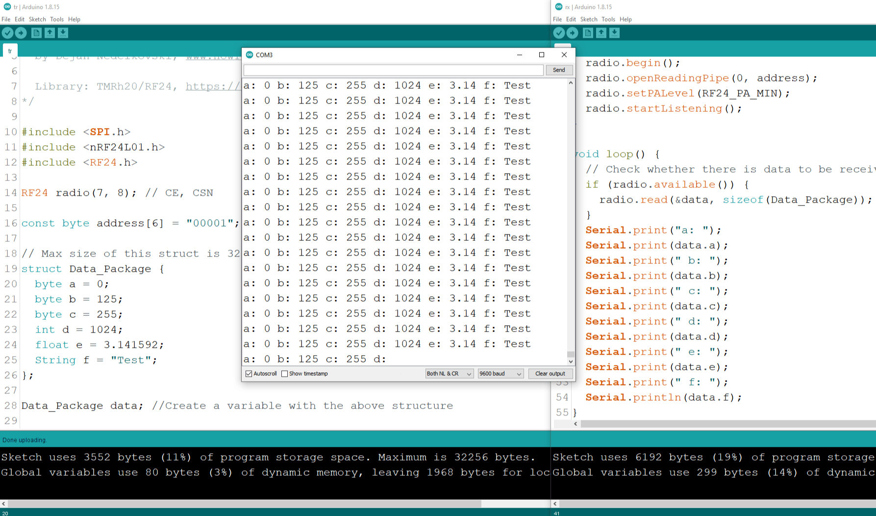
Data_Package data; // Create a variable with the above structureCode language: Arduino (arduino)We should keep in mind that the maximum size of this struct data can be 32 bytes. Here we can see I included three variables type byte, one integer variable (4 bytes), one float variable (4 bytes) and one String containing four characters (4 bytes). That’s total of 15 bytes.
Receiver Code
/*
  Arduino Wireless Communication Tutorial
        Example 1 - Receiver Code

  by Dejan Nedelkovski, www.HowToMechatronics.com

  Library: TMRh20/RF24, https://github.com/tmrh20/RF24/
*/

#include <SPI.h>
#include <nRF24L01.h>
#include <RF24.h>

RF24 radio(7, 8); // CE, CSN

const byte address[6] = "00001";

// Max size of this struct is 32 bytes - NRF24L01 buffer limit
struct Data_Package {
  byte a = 0;
  byte b = 125;
  byte c = 255;
  int d = 1024;
  float e = 3.141592;
  String f = "Test";
};

Data_Package data; //Create a variable with the above structure

void setup() {
  Serial.begin(9600);
  radio.begin();
  radio.openReadingPipe(0, address);
  radio.setPALevel(RF24_PA_MIN);
  radio.startListening();
}

void loop() {
  // Check whether there is data to be received
  if (radio.available()) {
    radio.read(&data, sizeof(Data_Package)); // Read the whole data and store it into the 'data' structure
  }
  Serial.print("a: ");
  Serial.print(data.a);
  Serial.print(" b: ");
  Serial.print(data.b);
  Serial.print(" c: ");
  Serial.print(data.c);
  Serial.print(" d: ");
  Serial.print(data.d);
  Serial.print(" e: ");
  Serial.print(data.e);
  Serial.print(" f: ");
  Serial.println(data.f);
}Code language: Arduino (arduino)
At the receiver side, we have to define the same struct data in order to be able to receive the incoming data. For testing whether the wireless communication works properly, I printed each variable on the serial monitor.
Conclusion
The NRF24L01 module is a great option for when you need wireless communication for your Arduino project. I have already used this module in many of my Arduino projects.
Here I will list all of my projects in which I have used these modules.
- Arduino Robot Car Wireless Control using HC-05 Bluetooth, NRF24L01 and HC-12 Transceiver Modules
- Arduino Wireless Weather Station Project
- DIY Arduino RC Transmitter
- Arduino Ant Hexapod Robot
- DIY Arduino based RC Hovercraft
- Arduino Mecanum Wheels Robot
- DIY Arduino RC Receiver for RC Models and Arduino Projects
- Arduino RC Airplane | 100% DIY
Each of these projects/ tutorials has a detailed explanation how to use the NRF24L01 module, including circuit diagrams, improved code implementation for better communication and so on.
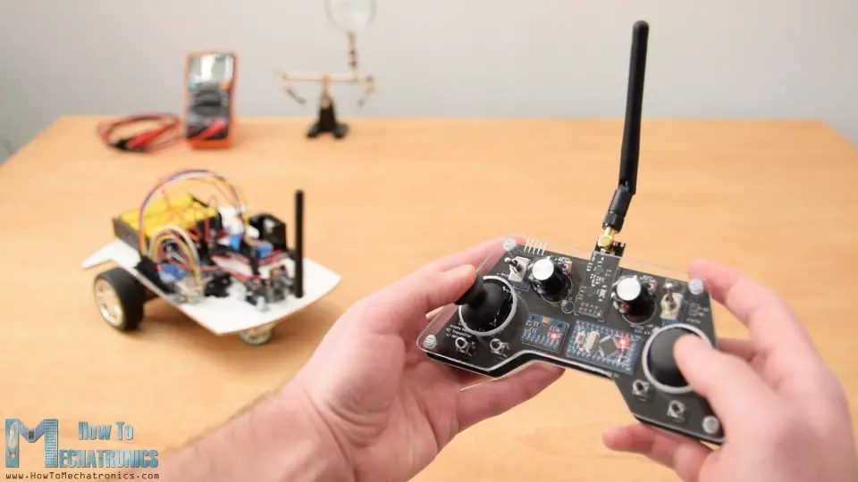
My favorite project is this custom designed Arduino RC Transmitter. It’s actually a 14-channel RC controller which can be used for controlling pretty much any Arduino Project.
That’s all for this tutorial, I hope you enjoyed it and learned something new. As always, feel free to ask any question in the comments section below.
PROJECT works like a charm! Thank you so much.
Glad to hear it!
Hi, thanks for the tutorial, exactly what I needed! Thanks also to the other commenters who helped explain the pins required for the Nano. I am using 10uf decouple capacitors across 3.3v and gnd.
I have an issue; when unplugging my computer from the Nano usb, the power drops. The onboard LED goes dim, and the program is no longer functional. Is the receiver too much power for Nano to supply? Do you have any suggestions?
I didn’t understand you well. How do you power the Nano, through the USB and the receiver from the 3,3V? The Nano 3.3v is might not be able to supply enough power for the receiver in some cases. You could use external power for it. However, usually the power supplies are 5V, so you would need a voltage regulator to convert the 5V to 3.3V. You can check the RC Transmitter project to see how I power the NRF24L01 module in that case, with the power coming from the external source (the battery), it goes to the AMS1117 3.3v voltage regulator which actually powers the receiver.
Thanks for a great tutorial – you make programming look so easy.
During my test of the 2 way communication I have experienced a small problem I just can’t figure out. I changed the receiver program to print the received value in the serial monitor. But the transmitting only starts when I open the serial monitor in the transmitter program. When transmitting has started I can disconnect USB and it keeps running.
Setup: 2 Nano with nRF addons. External 3.3 V, External 12V. Capacitor mounted on each nRF board. All common ground.
Beats me.
More testing/trouble shooting – More information.
Just to clarify – Both nanos are running on the same computer on two different COM ports.
It seems like the problem disappears if I’m powering up the transmitter nano with the USB disconnected. Then it starts transmitting straight away. Lesson learned: Maybe I don’t fully understand the COM ports. If somebody has a explanation I’m very keen to read it.
AWESOME!!!!! After a lot of examples, this one finally worked. The notorious NRF modules kept me guessing if I had any trouble in hardware/ power supply. Seems I did not. Thanks. Always cool projects !!
Sir, Thank you so, so much for your tutorial. You have a gift and sharing it is most appreciated. I am using using two nanos, one receive and one transmit, to monitor several parameters: current, accumulated charge, temperature and battery voltage of a solar powered sign that is very difficult to reach, can I say near-impossible to reach.
After struggling, mightily and unsuccessfully, to use use strings for data transmission I decided to use an additive offset to identify the data reads. e.g. 10,000 + AD count (or volt) , so that 101024 would be channel 1; 200256 would be channel 2, and so on. Then decoding is easy. Old school, yes; but it appears to be working and this comment may help someone else . Once again, thank you so very much.
jon
Thanks for the tutorial! I have a question regarding radio.setPALevel. You stated that you set it to the min level since the transceivers were close to each other. So my question is, does the setPALevel function as a determining factor for the range of which transceivers send out frequencies? Or to better specify, does the function allow one to determine how close you need two transceivers to be to allow for communication?
The “PA: stands for Power Amplifier and it correspond to the output level of the module. The higher is set, better range will have but that also means it will use more power. So if power consumption is an important factor for your project you should keep it at minimum, but of course it also depends on the range you want to achieve.
Dear Dejan,
Thank you for your excellent tutorials! I wish you continue sharing your knowledge!
Best regards, Gyuri
Hi
Thanx for the tutorial
Can I connect CE and CSN to non PWM pins like D7 and D8?
I want to use PWM pins for more options
Hey, yes you can use non PWM pins for the CE and CSN.
Hello thanks for the tutorial,
I am wondering if there is a reason you chose pins 7 and 8 CE and CSN. Why not just 9 and 10 for instance?
Thanks
You can use any other digital pin for those.
Very useful tutorial, many thanks. Question: does it make sense to stop transmitting data when that data does not change? on the receiver side, I have a loop which reacts on changing data (position of joystick). so, as long as the joystick is pushed left, the value of the joystick actually does not change, so why sending its position continuously. When the joystick is not pushed, it sits in the zero-position, and we would still send this. Is that necessary for the receiver or can that be stopped, e.g. by comparing new and old value and jump over radio.write(&joystick, sizeof(joystick)).
Well, yeah I guess you can do that. It depends what you want to achieve with it, like power saving or so. In such a case it would be useful.
Great tutorial!! Actually, I really enjoy all of your ideas and articles.
In that on, I drop onto some small issue:
The given example did not run in the beginning. I download the latest rf24 library but still nothing sent, nothing get. Then, I replace:
from :> const byte address[6] = “00001”;
to :> const byte address[5] = “00001”;
and all run like charm. Have no idea was it my fault, or something is new in the last library. That is my observation, and the Arduino IDE is the last one. 1.8.something
Cheers
I tried several times but can’t get any values from ardiuno mega….. But its works on uno… I want mega as receiver… Check connection and all, all are good,… Anyone tells what happening on mega??????
That’s kind of weird. Maybe there is something wrong with your Mega board. Make sure you are using the correct SPI pins on the Arduino Mega. Also, as I always suggest, use decoupling capacitor at the 3.3v input pin of the module.
Just saw this issue, maybe already too late but might be helpful for other Mega users: On MEGA, you need to set digital Pin 53 to OUPUT and LOW even when using any other pin as your CE signal. Otherwise SPI communication will not work properly.
WOW! Great tutorials. I have been working a bit with Arduino’s now and your site has been extremely helpful. I did have a question about the NRF24L01 vs. ESP8266. Would the ESP8266 work as well as the NRF24L01? A friend gave me a couple to play with for a project and I have not really used them before?
Thanks, I’m glad you find them useful. To be honest, I don’t have much experience with the ESP8266 module so I couldn’t give you any proper answer right now. Cheers!
Hello Dejan. Great tutorial … thanks! I have zero experience with Arduino but I understand it is good for robotics prototyping and figured I would dig in to see if it will work for my use case. I was hoping you could confirm that my assumptions are correct:
1. Sketch can open a connection (serial?) to computer over the standard USB connector, and this single connection can be kept open for the duration of the sketch;
2. This connection is shared on the computer so that it is accessible to any app running on the computer (read/write), e.g. apps built in Java, .NET, GoLang, etc.;
3. Sketch can read from the connection and send commands to a NRF24L01 module to simulate the transmitter for an RC device;
Am I dreaming up something that isn’t currently possibly or that doesn’t exist?
Thanks in advance.
Hey, thanks! Well your assumptions are pretty good and correct.
Hey there please, my nrf24L01 works rarely some times it does work and some times it works!!! Can you suggest me any solution please i’m new to this things please……and i have also connected a 47uf capacitor to the power suply of the module but it is not working every time!!!!!!!!
Hey, what about the power supply, try to use an external power supply. The 3.3V power supply of the Arduino sometimes is not enough to power the module. Try to use a different dedicated power supply for the module. In such a case make sure you connect the ground pin of that power supply with the ground pin of the Arduino in order to work things properly.
Hi, I was able to make this work but instead of bi-directional communication, I wanna be able to control two servos with joystick. How can I modify the code and the pin connections to do that?
Thanks for the great tutorial! I’ve spent lots of time with these sorts of projects, but this is the first time I’ve played with Arduino. I couldn’t get it working at first because of a real dumb mistake I might be able to help others avoid. I assumed your little Arduino had the same pins as my Pro Mini Uno. That wasn’t so – my pin 13 was on the other side of the board. Once I realized that, and hooked up the wires by pin number rather than by your schematic, everything worked great.
Hey, thanks for the input!
Hi
If for some reason ( like while using an Arduino motor shield) digital pins can be blocked.
The SIP pins are available on ICSP header and can be used there but can I use analog pins like A0 and A1 for this line :
RF24 radio(7, 8); // CE, CSN
Thanks for the tutorial. I was able to have it up and running in no time! I one question though, so with the transmitter code I am useing a mega2560 as well, but I am trying use a nano instead and whenever I put the pins that are normally on the 50, 51 and 52 pins of the mega2560 and put them on like pins 13, 12 and 11 of the nano, even just the 13, 12 and 11 of the mega2560, it doesn’t work. For some reason they only work on pins 50, 51 and 52 for the transmitter, any way I can fix this?
The SPI pins of the Nano are SCK -13, MISO – 12, MOSI – 11. So if connected properly it should work the same as with the Mega. And make sure you use a capacitor right next to the module for stabilizing the power supply.
I switched the pins to the ones you said to and it worked. Thanks again!
Thank you very much..I’ve just made the project using 2 UNO boards…Very nicely explained …. 🙂
Great, nice to hear that! 🙂
Congratulations my friend, your videos and explanations have helped and motivated an immensity of students and professionals, thank you for sharing your knowledge, we thank you from the heart.
Thanks, I’m glad to hear that!
HI, this is exactly what i need for my DIY RC Plane. But I can’t get this to work with 2 arduino unos. Does the board matter, I looked up the corresponding ICSP pins for the Uno boards, I don’t know why it is not working. I would appreciate a helpful response, Thank You.
The boards doesn’t matter. Most of the time the problem is the powers supply. Make sure you have good 3.3V power source, maybe even external one, and use bypass capacitor for stabilizing it. Also try to distance a bit the two modules when communicating.
Hello
The first example, writing “Hello World” works with out problem.
But the second example is not working for me. I don’t know the reason.
I checked my wiring of the led, servo and joystick but no connection error and tried multiple time. But no receiving and transmitting. My rf module are very close to each other. When I upload the code to UNO and MEGA the servo moves at end of code uploading. But when I pus joystick and button nothing happens.
Is there any thing I need to consider?
Hey, what about capacitors, try to use capacitors near the modules VCC and GND and distance a bit the two modules.
Thanks for your reply. The problem was one of the nrf24l01 module was not working properly (it only receives, doesn’t transmit). It takes me long time to identify the problem. I use another nrf24l01 and it works with out problem.
Hi, Thanks for the video. I am facing an unusual problem. Here is part of the receiver code I am working with. The “Available” string is getting printed , but there is no content in the text variable. Its just blank. Please help
if (radio.available()) {
Serial.println(“Available”);
char text[32] = “”;
radio.read(&text, sizeof(text));
Serial.println(text);}
Hey, make sure you use a capacitors at the module VCC and GND and make sure you send the same type of data as you are receiving. Also try to distance the two modules at least a meter.
Thanks a lot for your work to stretch out the basic principles in an easy and comprehensive way to everyone. Once again I used one of your great tutorials for the first step to a new topic before diving into depth and realizing my own thoughts and ideas. I really can recommend your publications as a quick introduction to the “howto’s”.
Keep the ball rollin’…
Thank you so very much. I’m glad to hear this!
Hi,
Thank you for your tutorial. It gives me an alternative for wireless communication between devices.
May I know how can I increase the distance range, and does the devices need a direct line of sight or is it possible to communicate even there is/are obstruction in between?
Thank you.
You can increase the range by using PA LNA SMA Antenna. And of course, the communication is possible even if there are obstacles like walls, but in that way the range will be decreased.
Thank you, I have tried wireless connection using RF433MHz module. But when I try to obstruct their line of sight. It can’t receive the signal of the transmitter.
I have a follow up question. Please do correct me if I’m wrong, I’m using Arduino Pro Mini, the SPI pins will be; MOSI(11), MISO(12), SCK(13). Am I correct?
Excellent tutorial.
How can i communicate more then two Arduinos using NRf24L01. I am working on a project where i have LCD with each arduinos and there is no concept of master-slave in it. for example. Arduino A send message to arduino B and C and display that message on B and C LCD. and then B or C reply to A And A show the message on LCD.
This project is based on consensus control of multi-agent systems where every agent is responsible to control its own resources.
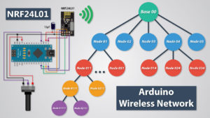
Thanks! Check my other tutorial for making a wireless network with RF24Network library.
I tried to make the nRF24l01 work, but the receiver code is just showing some random symbols even if the serial monitor baud rate is same as the code. Can you please tell me what might be the problem.
Thank you
Try to use decoupling capacitors and try to place the transmitter and the receiver at some distance, at least 1m.
Can we do the “Hello World” communication between two arduino in only one PC? means it’s only has one IDE. can we?
Yes you can do that. You just need to start the IDE two times, so you will have two different IDE on which you can select the different ports to which your Arduino are connected.
Many thanks for your great efforts, can i ask you how to do it if im using the HC 05 or HC 06 bluetooth moudles? im making an rc car and figured out how to drive the motors but i have one sevo on front intended for steering how can i code it?
Check my detailed Arduino Bluetooth Tutorial for the HC-05 Bluetooth module, you might find some useful information.
Thanks for such a great tutorial, I used the long range version of these to get about 400m using external PSU to create a long range door bell with reply function.
Hi, great tutorial, thank you! Is it possible to transmit from another source instead, say my own sensor with a 2.4GHz antenna, transmitting an analogue frequency. Then just use one Arduino and one nrf24I01 to receive and configure the data? Or will this module only communicate with another nrf24I01?
No, they can only communicate to each other.
Your example is really helpful but I am communicate both the nrf24L01 using getting started example but I am receiving garbage value instead of hello world. What can I Do?
Make sure they work at the same baud rate and your Serial monitor is set to the same baud rate.
Hi thank a lot for your example but i have a little problem maybe about the rf signal. i use uno r3 as transceiver and nano as receiver when i upload the code the data normally send and receive but after 30 sec it stop to send and receive the data could you pls help me out
The problem might be in the power. Try to use a capacitor to stabilize the power supply or try use an external power supply.
hello! great video! thank you for uploding, I have a problem my module doesnt recieve any data(I’m using arduino nano as tranciever and uno as reciever).I checked the wiring many times i tried it 100 ways to get it work but i haven’t succeeded yet.
Is there any oportunity with this library to check if the arduino can communicate with rf24 ? I searched in the RF24.h and i found a bool ChipIsConnected() but it doesnt return anything.
Try using a capacitor across the 3.3V and GND pins. The code library and the code I used for in this project are working 100%.
I am facing the same problem, have you reached any progress?
I have tried to use 10 micro Farad capacitor, but nothing changed. I still receive nothing.
could be the distance between the two modules…it is almost 10 cm max, because of the (PA _MIN).. try to bring them near to each others, or replace the _MIN with _LOW. if you have a capacitor connected, just remove the line in both sketches.
Good luck
Hello Dejan Nedelkovski
I read ” Arduino Wireless Communication – NRF24L01 Tutorial “. it is very useful for beginners. Thanks lot.
My problem is, how can I find ” nRF24L01.h” file ?
do you have a link for ” nRF24L01.h ? ”
thanks.
The link is included in this article already. You can find it right under the “Arduino Codes” section.
Thanks for the tutorial.
Do you have any ideas on how to establish a connection and receive data with a laptop computer rather than a second arduino?
Thanks
You can use a Bluetooth Module for that purpose. I already have a tutorial how to do it using a Bluetooth module.
Hi there!
I was able to make this project work. However, I am faced with an issue. Whenever I move the two Arduino boards (each with the NRF24L01 module attached in them), the signal gets lost. It was as if the modules can only work less than one meter in range? Unless I have missed something from the tutorial.
Thanks in advance for the reply.
Try to use decoupling capacitors or use an external power supply.
Excellent Tutorial, Thank you.
What resistor are you using in the second example though?
Thanks
Thanks. The two resistors used in the second example are 220 Ohms.
Well, I solved it by changing while (!radio.available()); to if (!radio.available());
works fine, good tut
Great, thanks!
Hi dejan
I have successfully trans communicated with mega 2560 to uno. … But my problem is the connection is not lasting for long time ..its just working for few seconds and stopping… Resetting on both boards Is also not working … When I disconnect two boards and connect them to power supply again its working for few seconds… But working time is different in each case….. Can you help me with this
The problem might be the power. Try to use more stable external power. These wireless module can be power hungry when transmitting data, so you might be losing the connection. Also try yo use decoupling capacitors.
hi all!
first, I want to congratulate dejan ’cause his tutos are wonderfull like sbdy say it before me!
in second, I’d the same problem of function-malfunction after two or three times using the joystick and it seems it was due cause using a non genuine uno.
when I change it for a genuine Arduino uno, the problem was solved… curious…
Hi. Wonderfull explanation. Q? Will system stand duplex if continuously move the joystick? In this case the program will be inside the while() function all time.
Thanks. It depends on the situation but it could work. You can notice in the introduction that I’m able to light up the LED while moving the joystick.
Your tutorials are just wonderful. I very much like the way you present them. Very clear and very helpful. Keep up, man!!
Thank you!
Hi , It is a good one .
Can we use arduino nano , UNO.
Thanks, you can use any Arduino.
if uno is used for transmitter, what are the replacement pins for 50,51,52 of the Mega?
Thanx
Arduino Uno SPI pins: 10 (SS), 11 (MOSI), 12 (MISO), 13 (SCK).
Hello, is your circuit diagram is wrong? The SCK of nrf2401 is not going to Pin 13 of arduino nano.
Hi Mr. Dejan,
I have already implemented this project using two Arduino NANOs.
Initially it was not working but after several hours of inspections I got a very important notice and would like to share it with all your follower. To get 2 NANOs wireless connected and communicating then auxiliary SPI pins must be used instead of D11, D12, and D13.
I finally got them working like dream. Thank you very much for sharing your lovely project. Cheers!
Can I extend the range to 200 meters by using a repeater. Master to repeater (slave/master) to other slaves and back?
Could be possible.
Hi, do you know any possible reason why my serial output is “yyyyyy yyyyyy yyyyy”???
Might be your serial monitor baud rate, check whether it matches with the baud rate set in the program.
Hi,how can send data for specific pipe and get answer from it.
Master have one address and if send data all slave get,s it?
I wont have one master that get data from 2 slave.
Thank you for sharing this very useful tutorial. Can you help me with the code to control More than one servo (I need to control 6 servo) using 6 potentiometer in one direction?
Well this shouldn’t be a problem, you just have to send those potentiometer values to the other Arduino and apply them to the servo motors. The same method would be used.
I really really appreciate this web thanks you ever so much
if you use a uno R3 board on the transmitter and receiver, what pins are you using for your push button and joystick, LED, and servo. have to set it up to understand how it works.
thanks,
The important thing is that you need to use the SPI pins of the Arduino board for the NRF24L01 module, or that’s the pins 13-SCKI, 12-MISO and 11-MOSI. For anything else, you can use any pin.
don’t go by diagram for Nano audrino go by written pin connection for 13… its good program… thanks to the programmer