In this Arduino Tutorial we will learn how to detect colors using Arduino and the TCS230 / TCS3200 Color Sensor. You can watch the following video or read the written tutorial below for more details.
How TCS230 / TCS3200 Color Sensor Works
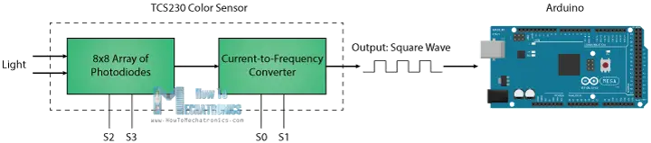
The TCS230 senses color light with the help of an 8 x 8 array of photodiodes. Then using a Current-to-Frequency Converter the readings from the photodiodes are converted into a square wave with a frequency directly proportional to the light intensity. Finally, using the Arduino Board we can read the square wave output and get the results for the color.
If we take a closer look at the sensor we can see how it detects various colors. The photodiodes have three different color filters. Sixteen of them have red filters, another 16 have green filters, another 16 have blue filters and the other 16 photodiodes are clear with no filters.
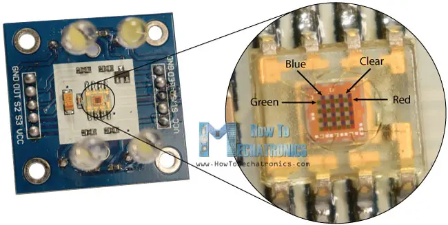
Each 16 photodiodes are connected in parallel, so using the two control pins S2 and S3 we can select which of them will be read. So for example, if we want to detect red color, we can just use the 16 red filtered photodiodes by setting the two pins to low logic level according to the table.
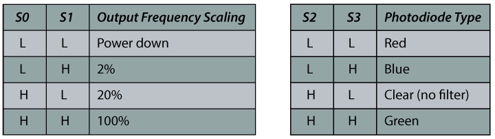
The sensor has two more control pins, S0 and S1 which are used for scaling the output frequency. The frequency can be scaled to three different preset values of 100 %, 20 % or 2%. This frequency-scaling function allows the output of the sensor to be optimized for various frequency counters or microcontrollers.
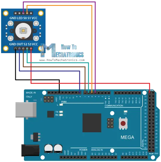
Now we are ready to move on and connect the TCS230 sensor to the Arduino board. Here’s the circuit schematics.
You can get the components needed for this Arduino tutorial from the links below:
- TCS230 TCS3200 Color Sensor……. Amazon / Banggood / AliExpress
- Arduino Board …………………………… Amazon / Banggood / AliExpress
- Breadboard and Jump Wires ……… Amazon / Banggood / AliExpress
Disclosure: These are affiliate links. As an Amazon Associate I earn from qualifying purchases.
TCS230 Color Sensor Source Code
Description: First we need to define the pins to which the sensor is connected and define a variable for reading the frequency. In the setup section we need to define the four control pins as outputs and the sensor output as an Arduino input. Here we also need to set the frequency-scaling, for this example I will set it to 20%, and start the serial communication for displaying the results in the Serial Monitor.
In the loop section, we will start with reading the red filtered photodiodes. For that purpose we will set the two control pins S2 and S3 to low logic level. Then using the “pulseIn()” function we will read the output frequency and put it into the variable “frequency”. Using the Serial.print() function we will print the result on the serial monitor. The same procedure goes for the two other colors, we just need to adjust the control pins for the appropriate color.
/* Arduino Color Sensing Tutorial
*
* by Dejan Nedelkovski, www.HowToMechatronics.com
*
*/
#define S0 4
#define S1 5
#define S2 6
#define S3 7
#define sensorOut 8
int frequency = 0;
void setup() {
pinMode(S0, OUTPUT);
pinMode(S1, OUTPUT);
pinMode(S2, OUTPUT);
pinMode(S3, OUTPUT);
pinMode(sensorOut, INPUT);
// Setting frequency-scaling to 20%
digitalWrite(S0,HIGH);
digitalWrite(S1,LOW);
Serial.begin(9600);
}
void loop() {
// Setting red filtered photodiodes to be read
digitalWrite(S2,LOW);
digitalWrite(S3,LOW);
// Reading the output frequency
frequency = pulseIn(sensorOut, LOW);
// Printing the value on the serial monitor
Serial.print("R= ");//printing name
Serial.print(frequency);//printing RED color frequency
Serial.print(" ");
delay(100);
// Setting Green filtered photodiodes to be read
digitalWrite(S2,HIGH);
digitalWrite(S3,HIGH);
// Reading the output frequency
frequency = pulseIn(sensorOut, LOW);
// Printing the value on the serial monitor
Serial.print("G= ");//printing name
Serial.print(frequency);//printing RED color frequency
Serial.print(" ");
delay(100);
// Setting Blue filtered photodiodes to be read
digitalWrite(S2,LOW);
digitalWrite(S3,HIGH);
// Reading the output frequency
frequency = pulseIn(sensorOut, LOW);
// Printing the value on the serial monitor
Serial.print("B= ");//printing name
Serial.print(frequency);//printing RED color frequency
Serial.println(" ");
delay(100);
}Code language: Arduino (arduino)Now if we run the Serial Monitor we will start getting some values. These values depend on the selected frequency-scaling, as well as from the surrounding lighting.
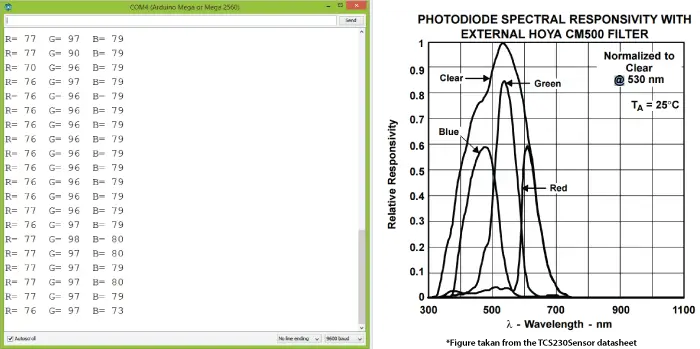
Note here that three values differ due to the different sensitivity of each photodiode type, as seen from the photodiode spectral responsivity diagram from the datasheet of the sensor.
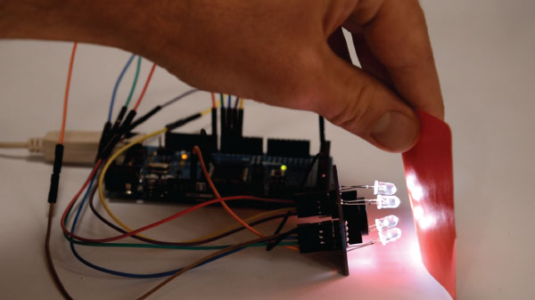
Nevertheless, now let’s see how the values react when we will bring different colors in front of the sensor. So for example, if we bring red color, the initial value will drop down, in my case from around 70 to around 25.
So now if we want to represent the detected colors with the RGB Model which has values from 0 to 255, we will use the map() function to map or convert the readings to the values from 0 to 255.
//Remaping the value of the frequency to the RGB Model of 0 to 255
  frequency = map(frequency, 25,70,255,0);
The value of 70 will be mapped to 0, and the value of 25 to 255. The same procedure goes for the two other colors.
Here’s the final source code for this example:
/*     Arduino Color Sensing Tutorial
 *
 *  by Dejan Nedelkovski, www.HowToMechatronics.com
 *
 */

#define S0 4
#define S1 5
#define S2 6
#define S3 7
#define sensorOut 8

int frequency = 0;

void setup() {
  pinMode(S0, OUTPUT);
  pinMode(S1, OUTPUT);
  pinMode(S2, OUTPUT);
  pinMode(S3, OUTPUT);
  pinMode(sensorOut, INPUT);

  // Setting frequency-scaling to 20%
  digitalWrite(S0,HIGH);
  digitalWrite(S1,LOW);

  Serial.begin(9600);
}

void loop() {
  // Setting red filtered photodiodes to be read
  digitalWrite(S2,LOW);
  digitalWrite(S3,LOW);
  // Reading the output frequency
  frequency = pulseIn(sensorOut, LOW);
  //Remaping the value of the frequency to the RGB Model of 0 to 255
  frequency = map(frequency, 25,72,255,0);
  // Printing the value on the serial monitor
  Serial.print("R= ");//printing name
  Serial.print(frequency);//printing RED color frequency
  Serial.print("  ");
  delay(100);

  // Setting Green filtered photodiodes to be read
  digitalWrite(S2,HIGH);
  digitalWrite(S3,HIGH);
  // Reading the output frequency
  frequency = pulseIn(sensorOut, LOW);
  //Remaping the value of the frequency to the RGB Model of 0 to 255
  frequency = map(frequency, 30,90,255,0);
  // Printing the value on the serial monitor
  Serial.print("G= ");//printing name
  Serial.print(frequency);//printing RED color frequency
  Serial.print("  ");
  delay(100);

  // Setting Blue filtered photodiodes to be read
  digitalWrite(S2,LOW);
  digitalWrite(S3,HIGH);
  // Reading the output frequency
  frequency = pulseIn(sensorOut, LOW);
  //Remaping the value of the frequency to the RGB Model of 0 to 255
  frequency = map(frequency, 25,70,255,0);
  // Printing the value on the serial monitor
  Serial.print("B= ");//printing name
  Serial.print(frequency);//printing RED color frequency
  Serial.println("  ");
  delay(100);
}Code language: Arduino (arduino)
Note that the colors aren’t that much accurate but they are still good enough for simple projects. As another example of the TCS230 color sensor in my next video we will learn how to make an Arduino Automatic Color Sorting Machine.

Feel free to ask any question in the comments section below and don’t forget to check out my collection of Arduino Projects.
Hello, i am anot student in engineering and we need to pick a colour sensor solution for a robot we are making.
The main iqsue as for now is that we don t know from how far we can sense colours with this kind of sensors, we only need to sense green.
We are on a budget so we can t really afford high quality sensors, do you have any ideas of the max distance/field of vue for arduino compatible sensors ?
Thank you for the guides !
Hey, the sensor range is relatively small, around 1cm to 3cm.
Hi,
How far can this sensor measure?
maximum range ?
The range is pretty small, around 1cm – 3cm.
In the code that has been written, the pulseIn(sensorOut,LOW) method returns the time for which pin 8 is low. It does not return the output frequency.
But this example is however as it gives a good method of using TCS3200.
https://www.arduino.cc/en/Reference.PulseIn
Hi,
Thanks for the tutorial. Does this sensor detects color under sunlight?
Well I guess yes, it should be able to detect color under sunlight.
Hi,
When connecting the TCS3200 can you use just regular digital pins or do it need to be connected to the PWM ports of the ARDUINO
Yes, you can use the regular digital pins.
hi can you please explain how to calibrate the color sensor ?
It’s kind a hard to calibrate because it’s a low quality sensor.
hi sir ,
we are stuck in calibration .how long we have to calibrate. sensor are not detecting the colour properly .so can you suggest how to rectify the problem .
Well yeah, the calibration is a problem, because the sensor often gives various readings for the same color. Try changing the environment lightning, add some more light around so it might work better, or maybe reduce the light.
Hello,
I’m having the same difficulty as Nguyen Khang above. My sensor hovers around the following for each sensor
R: 200
G: 350
B: 450
Granted we are in a room with bright office lighting. How would you recommend mapping these values? Just use a bigger range than yours (25-70)?
We’re using an arduino Uno by the way.
Well yes, you should adjust the ranges according your the values you are getting. This have to be done by manually testing each color you want to scan, and do that multiply times for getting more accurate or average values.
hello sir, your circuit connection is different with the codes. just concern it might confused other user.
Thanks for the remark, you are right. S0 should go to pin number 4, S1 to pin number 5.
HOW to make tcs3200 only to detect green color, ignoring red and blue? So that, if it detects green color green we have to run a motor.
Well just take into consideration the values from the sensor when reading the green color and use them to set the motor running.
Hi,
Can you please tell me how to make an LED illuminate the same color as the color recognized by the sensor?
and also, what ever the value is read, lets say R=255, G = 108, B = 20, put it in another function where a ratio is calculated?
Thank you.
Well you just need and RGB led and using the digital.Write() function send those values to each R, G and B pin. Check my Arduino RGB tutorial for more details how to use an RGB LED with Arduino.
Dear Mr. Dejan.
Thanks for your post. But I have some problems because our TCS has different Relative Responsivity. So my result don’t fall into 0 – 255 as I like.
Could you explain to me how do you get the interval of each color like you did, such as R (25;70) please. I can’t figure out how to get that. Thank you.
I’m looking forward to your reply.
The following line is used for converting the range from 25-70 to 0-255.
//Remaping the value of the frequency to the RGB Model of 0 to 255
frequency = map(frequency, 25,70,255,0);
I mean how can we know the range of the sensor is between 25-70 ? Because my sensor gave me the totally different data.
Hi Dear Mr.Dejan Nedelkovski
Thanks for your post. But i dont understand about S0, S1 and the output frequency scaling. What does it show? and in the 1st code, why you setting frequency scaling to 20%?
Thanks,
The frequency can be scaled to three different preset values of 100 %, 20 % or 2%. This frequency-scaling function allows the output of the sensor to be optimized for various frequency counters or microcontrollers. In other words depending on the selected value it will produce different output signal.
With your code i get values like:
“R= 245 G= 382 B= 170
R= -292 G= 382 B= 182
R= -292 G= 382 B= 187
R= -292 G= 382 B= 182
R= -292 G= 382 B= 170
R= -292 G= -875 B= 193
R= -282 G= 382 B= 204
R= -271 G= 217 B= 210
R= -271 G= 221 B= 216
R= -184 G= 382 B= -640
R= -43 G= -2579 B= -11951
R= -1101 G= -3162 B= -11622
R= 55 G= -2915 B= -11401
”
I Dont know whats happening there. I have a smaller arduino and connected all to Analog pins. The LED’s are on.
You should connect it to digital pins.
Good job Dejan. Thanks.
I’m really enjoying getting to know the sensors for the Arduino. The generosity of guys like you, posting helpful material like this makes it so much quicker to learn.
I wish now that I hadn’t bought the TCS3200 board before I read your guide or I would definitely have clicked through to Amazon from here.
All the best, David
Thank you!
Hello.
Am I right to assume those are just regular white LEDs? I have a TCS3200 that came with the leds already soldered, but they are too short and I need it to have a smaller field of view. Can I just remove those leds and solder new ones?
Thank you, very useful website!!
Yes, the are regular LEDs and you should be able to replace them.
Hi Dear Mr.Dejan Nedelkovski
I tested this example it’s work,but i couldn’t understand how to map color valve,
Red 25~37 to map 0 ~ 255
Green 30~90 to map 0 ~ 255
Blue 25~70 to map 0 ~ 255
How to gate those (25~37,30~90,25~70) value
please help me to understand how to change those value
Thank you
BR
Sahan kalhara
Hi there. Did you try using the following function for mapping values: map(variable, fromLow, fromHigh, toLow, toHigh)?
The formula is (variable, fromLow, fromHigh, toLow, toHigh) or (variable, fromLow, fromHigh, toHigh, toLow) because in coding is write frequency = map(frequency, 25,70,255,0);
That’s a good note. The formula is more like (variable, fromValue1, fromValue2, toValue1, toValue2) and the reason the code line is frequency = map(frequency, 25,70,255,0) is because we want to reverse the values.
Nice video,
I have a TCS3200, and where does the LED pin go to ? Your video shows that the LED is lit, but you have not connected the LED output to anything in the picture uploaded in this web page ?
How did the LED on the TCS 230 light up ? In my case, the LED does not light up as it is NOT connected. Appreciate a reply.
Thanks. Well in my case the LEDs light up by just connecting power to the VCC pin. Did you try connecting 5V to the LED pin of the module, did you get your LEDs light up?